Hi,
Thought I move my previous question in different topic and share the finding here.
So I bought a MAX7219 and was playing around with the spi-tool. Looking at Arduino code and also 7219 datasheet able to do the following
// set scan limit
spi-tool -b 0 -d 1 write 0x0B 0x0f
// set power ON
spi-tool -b 0 -d 1 write 0x0C 0x1
// decode mode
spi-tool -b 0 -d 1 write 0x09 0xFF
// test mode
spi-tool -b 0 -d 1 write 0x0F 0x1
with the test mode (0x0F) able to turn on all the LED and to turn of use 0x0 for 0x0F register.
But the funny thing is when I use the write command to write on the first row like so
spi-tool -b 0 -d 1 write 0x00 0x01
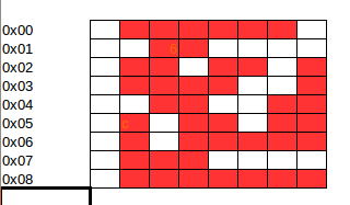
I see 2 LED turned on in Row 0 which is not right. I'm attaching diagram of which LED turn on when using the following command
spi-tool -b 0 -d 1 write 0x00 <value>
Any idea why the LED is not turn on properly ?
Tested in Arduino and all works fine. I tested with Arduino using the sample code from here https://brainy-bits.com/tutorials/how-to-control-max7219-led-matrix/


