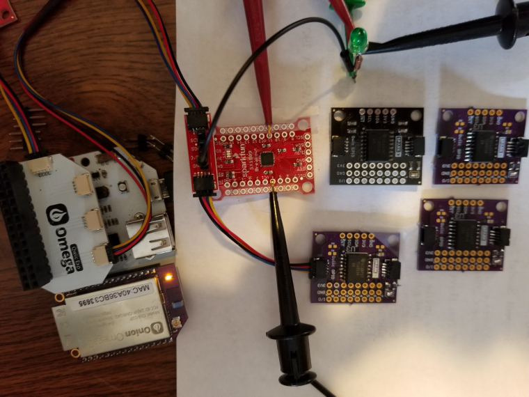
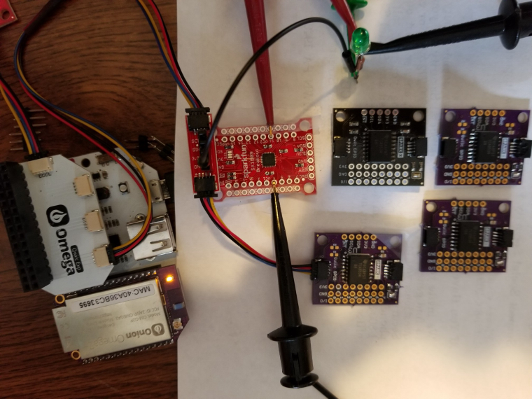
@Angus-Ryan Did you solve your problem? I had something similar with the Dock 2 and a 3.5" TFT display. The problem was a conflict between I2C communication between the omega and the Dock's AVR chip with uses pins A4 and A5. But the pin corresponding to A4 resets the TFT display, So I cut this pin on the display and wired it to the Tx pin on the Dock 2, to do a hard reset when needed, but not during I2C transfers. The other added wire in the picture enables GPIO11 to receive data from the Arduino, but that is unrelated to the flakey operation I had before cutting the reset pin on the display.
Hope that's helpful.
Yale E. Goldman
@Yale E. Goldman
Best posts made by Yale E. Goldman
Latest posts made by Yale E. Goldman
-
RE: Touch Screen with Omega2+ and Arduino Dock 2posted in Projects
-
Programming Arduino Dock 2 via SPIposted in Omega Talk
I have several Arduino Dock 2 boards and for some of them when trying to program the
Arduino AVR chip on the Dock using the Omega (2+), they give an error message "Communication Failure". Other Dock 2 boards of the same typ work fine. For the ones that are not working I am trying to program them using a spare Arduino Uno as a programmer. I successfully program one Uno from another Uno using the SPI signals as instructed here:
https://www.instructables.com/Programming-Arduino-With-Another-Arduino/That works fine, so I connected the non-working Dock 2 using the same wiring scheme (11, 12, 13 SPI lines, 10 from programmer to reset on the Dock 2 and 5V pwr and gnd). There is no Onion Omega plugged into the Dock2. I have ArduinoISP loaded into the Uno and I try to upload Blink.ino by clicking 'Upload using Programmer". It seems to write to the Dock2 and tries repeatedly to read and verify the code, then issues the following error message:
avrdude: Device signature = 0xffffff (probably .avr8x_mega)
avrdude: Yikes! Invalid device signature.
Double check connections and try again, or use -F to override
this check.It's the same whether I set "Arduino Uno" or "Onion Arduino Dock" as the target board.
If I run avrdude from the command line with the -F switch as
avrdude -F -C../etc/avrdude.conf -v -patmega328p -cstk500v1 -PCOM8 -b19200 -Uflash:w:C:\Users\GOLDMA~1\AppData\Local\Temp\arduino_build_728892/Blink.ino.hex:i
it gets further, but then gives this new error:
avrdude: verifying ...
avrdude: verification error, first mismatch at byte 0x0000
0xff != 0x0c
avrdude: verification error; content mismatchavrdude: safemode: hfuse reads as FF
avrdude: safemode: efuse reads as FF
avrdude: safemode: Fuses OK (E:FF, H:FF, L:FF)A similar error comes back if I try to load a bootloader into the Docks with the Arduino "Burn Bootloader" command.
Would someone provide detailed instructions for programming the AVR chip on an Arduino Dock 2 via the SPI interface or from a spare Arduino?
Thanks.
-
RE: Read I2C 16-bit addressesposted in Omega Talk
I hadn't finished and it submitted somehow.
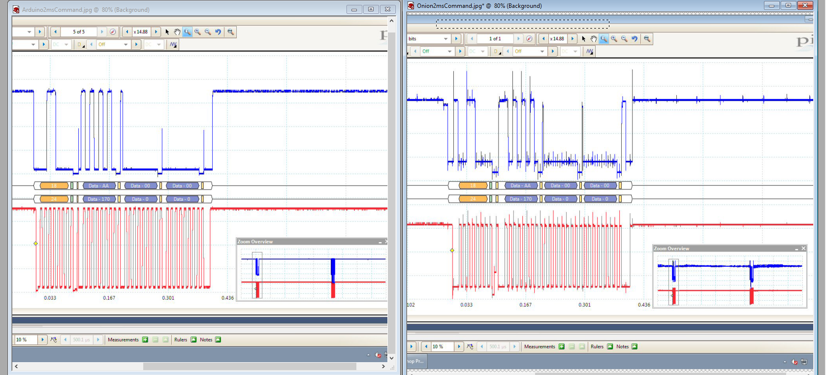
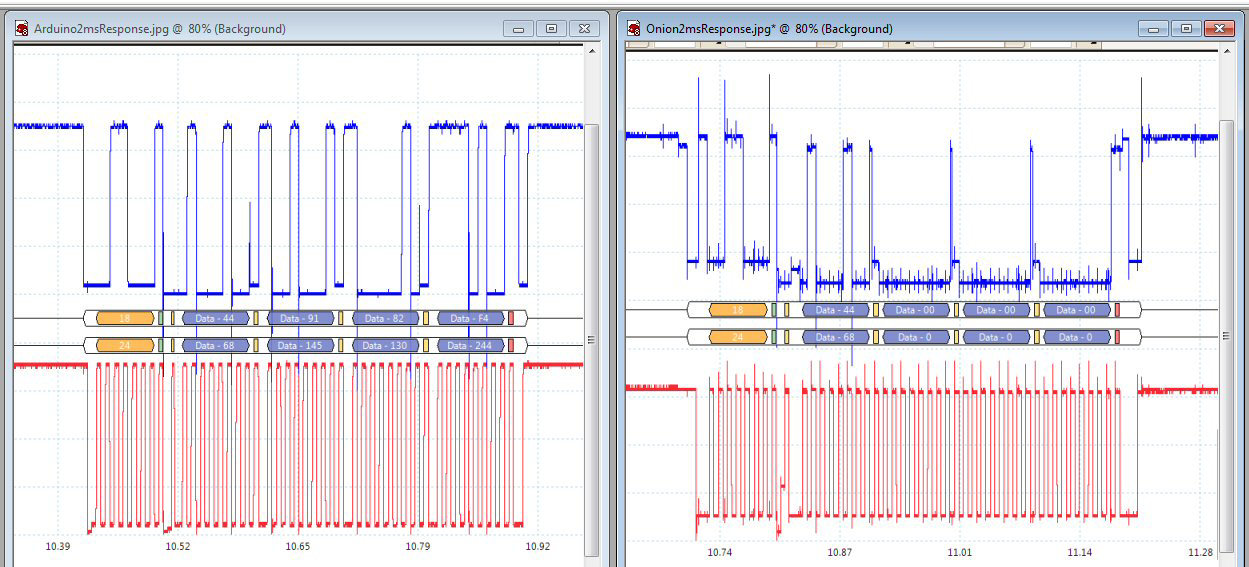
The Python code is:bytes = [0xAA, 0, 0] try: i2c.write(0x18, bytes) except: print "write failed" time.sleep(0.01) y0 = i2c.read(0x18,4) print y0This returns a status byte, but zeros for the pressure data. The i2c waveforms which I captured from an oscilloscope look different enough to matter. Can I upload them here somehow?
The command bytes to read the pressure [0xAA, 0x00, 0x00} for Arduino and Onion:

And the two responses showing that the sensor only returns zeros on the Onion

The oscilloscope interprets all of the i2c bus traffic correctly, but it appears that the sensoe is never getting triggered by the [0xAA...] command to start digitizing. So it only sends back zeros. Does anybody know why the i2c waveforms are different and how to make the Onion i2c library behave as the Arduino does which works properly. I am not having any trouble with other i2c communication from the Onion, only this sensor.
Thanks to anyone who is up on this.
Stay safe!
Y. -
RE: Read I2C 16-bit addressesposted in Omega Talk
Hi Lazar,
Thanks so much. The command i2c.read(0x18, 4) no longer issues an error and it does read 4 bytes from my sensor. I am still having trouble with it, though. Not sure if you or anyone can help with this, but here goes: I am trying to access an Adafruit MPRLS pressure sensor. It works fine with an Arduino voltage-shifted to 3V with a Quiic shield. But not through the Quiic expansion header on the Omega2. A read command is [0xAA, 0x00, 0x00]. The two code snippet are here: Arduino:
byte raw[3];
Wire.beginTransmission(0x18);
Wire.write(0xAA); // command to read pressure
Wire.write((byte)0x0);
Wire.write((byte)0x0);
Wire.endTransmission();

delay(10);

Wire.requestFrom(0x18, 4);
uint8_t stat = Wire.read();
// Serial.println("Reading");
raw[0] = Wire.read();
raw[1] = Wire.read();
raw[2] = Wire.read();That works fine and gives appropirate pressure reading in a 24-bit word in raw[0] thru raw[2].
The Python code on the Onion is supposed to be equivalent:
try:
	i2c.write(0x18, bytes)
except:
	print "write failed 1"
'''
i2c.write(0x18, [0xAA])
time.sleep(0.01)
i2c.write(0x18, [0])
time.sleep(0.01)
i2c.write(0x18, [0])
'''
time.sleep(0.01)

'''
y0 = i2c.read(0x18, 1)
print y0
i2c.write(0x18, bytes)
time.sleep(0.01)
'''
time.sleep(0.005)
y0 = i2c.read(0x18,4)
print y0
i2c.write(0x18, bytes)
time.sleep(0.05)
-
RE: Read I2C 16-bit addressesposted in Omega Talk
@Lazar-Demin said in Read I2C 16-bit addresses:
i2c_readRaw()
Hi Lazar,
Thanks for the reply. But it looks like i2c_readRaw() is a C subroutine, not a python command. For instance in the code here:
from OmegaExpansion import onionI2C
import time
i2c = onionI2C.OnionI2C()
while (1):x = i2c.readBytes(0x20, 0x03, 1) time.sleep(0.1) y = i2c.i2c_readRaw(0x20) print x, y time.sleep(1)the line defining 'x' works fine, but the one trying to read without a register
returns the message "Attribute error: 'OnionI2C' object has not attribute 'i2c_readRaw' "
Can I access the readRaw function from Python?All the best.
-
RE: Read I2C 16-bit addressesposted in Omega Talk
You can find the earlier thread by searching for "I2C: how to read a single byte without register address?"
-
RE: Read I2C 16-bit addressesposted in Omega Talk
I'm having a related problem. Using Python to access a pressure sensor, Adafruit MPRLS, takes a single byte address (fixed at 0x18), but to read its register, requres a direct 4-byte read with no address register or instruction register on the chip. The Onion i2c implementation doesn't seem to have a routine for this register-less read function. There was some discussion of this problem in the forum earlier and people used an SMBus implementation, but it was not described well enough for me to follow. Has anyone solved this problem and can explain the solution? Or else an updated official PyOnionI2C package that can read a slave just using its bus address (e.g. 0x18) without specifying a register? Thanks.
-
Sparkfun I2C GPIO expanders 2posted in Projects
[0_1576345075178_Qwiic_GPIO.brd](Uploading 100%) This goes with an earlier post on Sparkfun I2C GPIO expanders. A 2nd Sparkfun device is the Qwiic GPIO, SPX-14716, which uses a TCA9534 I2C chip. An advantage is that Qwiic connectors are already mounted on this device. This was an experimental board and is not directly available any more. However, Chris at the Sparkfun help desk gave me the Eagle file for the board. He will allow me to distribute it, but I don't see how to uploae it here. At https://oshpark.com/, I was able to obtain 6 of these boards for $12.00 and the ICs from Digikey: PART: 296-47827-1-ND MFG : Texas Instruments (VA) / TCA9534DWR. Hand soldered the components an they all worked fine. Some are shown (the darker boards) in this pic:
 .
.
Python code for accessing them is here:# adapted from <https://github.com/topherCantrell/pi-io-expander/find/master> from OmegaExpansion import onionI2C #need >>opkg install python-light pyOnionI2C import time CHIP_A = 0x27 # I2C address for chip A, cut jumpers for other addresses TC_RegDataIn = 0x00 # default 0xxx TC_RegDataOut = 0x01 # default 0xFF TC_RegPolInv = 0x02 # default 0x00; polarity invert TC_RegConf = 0x03 # default 0xFF, 1 = input; 0 = output; configuration bus = onionI2C.OnionI2C() bus.writeByte(CHIP_A, TC_RegConf, 0xFF-0x04) # set bit 2 as output; e.g. 1111 1011 while True: bus.writeByte(CHIP_A, TC_RegDataOut, 4) #bit 2 on a = bus.readBytes(CHIP_A, TC_RegDataIn, 1) # print(a) print a[0] # a is a list even though it's only one byte time.sleep(0.2) bus.writeByte(CHIP_A, TC_RegDataOut, 0) # all off a = bus.readBytes(CHIP_A, TC_RegDataIn, 1) print a[0] time.sleep(0.2) print -
Sparkfun I2C GPIO expandersposted in Projects
I needed extra GPIO pins, so I tried two of Sparkfun's I2C offerings. One is SparkFun 16 Output I/O Expander Breakout - SX1509, BOB-13601. By stacking a SparkFun Qwiic Adapter, DEV-14495, on top I connected the GPIO expander to the Omega Qwiic expansion as shown in the picture.
 . Driver software for this board and Python in the raspberry Pi environment is here: https://github.com/topherCantrell/pi-io-expander/find/master, which was easy to adapt for simple I/O. The Onion Omega Python-light version is here:
#!/usr/bin/env python

# adapted from <https://github.com/topherCantrell/pi-io-expander/find/master>

from OmegaExpansion import onionI2C #need >>opkg install python-light pyOnionI2C
import time

CHIP_A = 0x3E # I2C address for chip A, cut jumpers for other addresses

SX_RegDirA = 0x0F # Data direction registers...
SX_RegDirB = 0x0E # ...default 0xFF, 0 is output, 1 is input

SX_RegDataA = 0x11 # Data value registers...
SX_RegDataB = 0x10 # ...default 0xFF

SX_RegPullDownA = 0x09 # Registers to enable pulldown resistors...
SX_RegPullDownB = 0x08 # ... default 0x00, 0 is disabled, 1 is enabled

bus = onionI2C.OnionI2C()

#bus.writeByte(CHIP_A, SX_RegDirA, 0xFF)     # That's the default, so not needed
#bus.writeByte(CHIP_A, SX_RegDirB, 0xFF-8)   # Just bit 11 as output. e.g. 1111 0111
bus.writeByte(CHIP_A, SX_RegDirB, 0xFF-0x09) # Set bits 8 and 11 as outputs, e.g. 1111 0110

bus.writeByte(CHIP_A, SX_RegDataB, 8) # Switch on pin 11
time.sleep(1)
bus.writeByte(CHIP_A, SX_RegDataB, 0) # Switch p1n 11 off

while True:

	bus.writeByte(CHIP_A, SX_RegDataB, 8) # Switch on pin 11
	a = bus.readBytes(CHIP_A, SX_RegDataB, 2)
	print a[0], ',', a[1]
	time.sleep(0.2)

	bus.writeByte(CHIP_A, SX_RegDataB, 1) # Switch pin 11 off and pin 8 on
	a = bus.readBytes(CHIP_A, SX_RegDataB, 2)
	print a[0], ',', a[1]
	time.sleep(0.2)

	bus.writeByte(CHIP_A, SX_RegDataB, 0) # All off
	a = bus.readBytes(CHIP_A, SX_RegDataB, 2)
	print a[0], ',', a[1]
	time.sleep(0.2)
	print ' '
Another post describes a different GPIO expander.
-
RE: Simple PHP-Web-Gpio example switching ledsposted in Projects
@Lazar-Demin Hi Lazar, After opkg update, php5-cgi installed and I was able to run PHP srcipts, like SwitchLeds and others. Thanks for the help. I had recently done the opkg update, so how often does it need to be run?