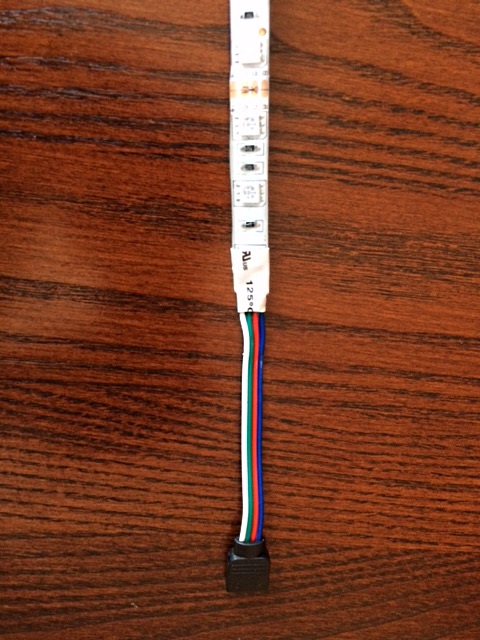
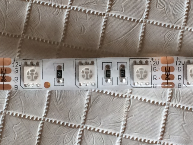
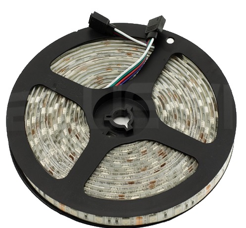
Multi-color (RGB) LED lightstrips seem to be very popular at the moment, so I set out to control them with an Omega. The strips I purchased seem to be wired much the same as the majority of lightstrips: all LED anodes are tied together to a common node (+12V for my strips), while the cathodes of each color are also tied together, but at the other end of a current limiting resistor. Therefore my lightstrips have a white wire connected to a node labeled +12V, and there are red, green, and blue wires corresponding to the common connections for the red, green, and blue LEDs (respectively). If I connect a power supply such that 12Vdc is applied to the +12V wire and then connect the red wire to the power supply's ground (0V) terminal, all of the red LEDs in the strip light up, with around 180mA flowing. Similar results are achieved for grounding the blue wire or green wire, with typical current around 160 to 180mA. The Omega's GPIO pins can't handle this much current, so I used a simple interface circuit, one for each color (and tying the power supply's ground (0V output) to the Omega's ground:

To control the LEDs, I just issue a fast-gpio pwm command like this:
fast-gpio pwm 14 200 50
This command produces a 200Hz square wave output with 50% duty cycle at GPIO14 (where I have my red LED interface circuit connected). Similarly, I have the interface circuits for green and blue connected to GPIO23 and GPIO26, respectively. So for example, to produce violet at a relatively low brightness, I can issue the commands
fast-gpio pwm 14 200 20
fast-gpio pwm 23 200 0
fast-gpio pwm 26 200 20
I have noticed that setting the duty-cycle to 0 doesn't actually produce a 0% duty-cycle, but there are actually very short pulses output (probably intended to keep servos "happy"), so the command
fast-gpio pwm 23 200 0
actually causes the green LED to glow very dimly. However, since the red and blue LEDs are operating at 20% duty-cycle, the green isn't really noticeable. To remedy this situation, you can use a number above 100 to turn a given color OFF. To save from having to issue a full fast-gpio command for each color, I wrote the following sh script:
#!/bin/sh
if [ $1 -gt "100" ]
then
   echo "value is over-range"
   echo "use a whole number from 0 to 100"
elif [ $1 -lt "0" ]
then
   echo "value is under-range"
   echo "use a whole number from 0 to 100"
elif [ $1 -eq "0" ]
then
   fast-gpio pwm 14 200 101
else
   fast-gpio pwm 14 200 $1
fi
I saved the script under the filename red, and made similar scripts for green and blue, substituting 23 for 14 in the green script, and 26 for the blue script. I also typed
chmod 744 red
chmod 744 green
chmod 744 blue
to give me (the file owner) execute permissions for each script. So now, for example, to get a violet color at around medium brightness, I type the following at the user prompt
red 50
blue 50
green 0
The scripts check to make sure that the user types a value between 0 and 100, and also substitutes 101 for 0, as noted above, to turn a given color off. I recently used this light strip to decorate a table at an event, and the effect was very well received.
Note: With the LED strips I've tested, a 50% duty cycle is actually a lot brighter to me than halfway between fully on (100% duty-cycle) and fully off. I actually used a duty-cycle value of around 30 to achieve a medium brightness.
Also, the 20k resistor in the circuit is not strictly necessary if the circuit is connected to GPIOs set as outputs. This resistor is used to keep the driver turned off if the GPIO pin is left as an input (high impedance) without internal pull-ups or pull-downs (the default state for most of the GPIOs upon boot-up.


