MCP3008 SPI Addressing and 0x00 returned values
-
Hi,
I've been having issues using an MCP3008 with the Omega2. I saw this post: Using a MCP3008 via SPI, and am also having issues. I'm trying to read channel 0 on the ADC.That post mentioned sending the command word 1100 or 11000000 to read from the device, however my attempts were unsuccessful. I used the following command:
res = spi.readBytes(0xC0,1)I consistently get 0x00 as the returned value , when attempting a whole range of different addresses (not just 0xC or 0xC0).
My specific questions are:- Am I addressing channel 0 correctly?
- What should I check if I keep getting 0x00 as the readBytes returned value?
Thanks!
-
I have not used SPI, but according to this post, it is not reliable.
-
Actually,
0xC0would be transmitted correctly in all cases. In my tests, byte values from0x40to inclusive0xbfare wrong, and0xC0is just one above that. I'll get an Arduino, my Omega2 and a MCP3008 today, will attempt to read out the channel 0 with both devices, and compare SPI transfers with my logic anyalzer. After that, I will be able to tell you if the software is wrong or if the SPI failed. There are many factors involved, like hardware and sofware alike software (e.g. SPI configuration (speed, bit length of transfers, SPI mode 0 to 3,...)).
-
Update: I can successfully read the ADC's values with an Arduino Nano and my Omega2+. I ported https://github.com/adafruit/Adafruit_MCP3008 to C for the Omega.
The interesting bit is the requesting the ADC value: You have to read the datasheet very carefully, there is section 6 about reading data using a MCU. Your command byte
0xC0is correct, but you have to send two0x00bytes to read the 10-bit response.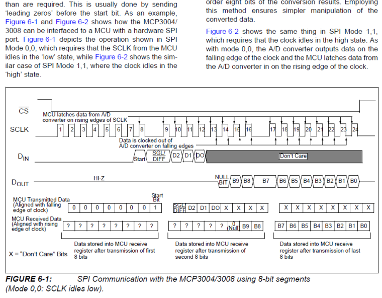
Anyways, here is the C code.
MCP3008.c/* MCP3008.c * * This file contains functions for letting the Omega interact with an MCP3008, * a 8-channel 10 bit ADC. * * Ported by: Maximilian Gerhardt, January 2018. */ #include "MCP3008.h" #include <stdio.h> #include <stdbool.h> #include <unistd.h> /* for slep() */ #include <onion-spi.h> /* main SPI functionality */ #include <onion-debug.h> /* debug output */ /* Global SPI object. Can only have 1 user at a time. */ static struct spiParams params; /* Depending on the given VDD voltage, the MCP3008 supports a different maximum SPI clock speeds. */ #define MCP3008_SPI_MAX_5V 3600000 #define MCP3008_SPI_MAX_3V 1350000 #define MCP3008_SPI_MAX MCP3008_SPI_MAX_3V /* Select the 3.3V version*/ static int SPIxADC(int channel, bool differential); /* Initialize the SPI bus on the given GPIO pins. * On the MCP3008, these pins are called D_out, D_in, CLK, /CS/SHDN * */ bool MCP3008_Startup(int miso, int mosi, int sclk, int cs) { int err = 0; //Start initializing the SPI bus. spiParamInit(¶ms); params.misoGpio = miso; params.mosiGpio = mosi; params.sckGpio = sclk; params.csGpio = cs; params.speedInHz = MCP3008_SPI_MAX; params.modeBits = SPI_MODE_0; params.busNum = 1; //this comes from my local machine. no idea if it works elsewhere.. (ls /dev/spi*) params.deviceId = 32766; params.delayInUs = 10; //is our device already mapped? err = spiCheckDevice(params.busNum, params.deviceId, ONION_SEVERITY_DEBUG); if(err == EXIT_FAILURE) { printf("[-] spiCheckDevice() failed.\n"); return false; } //register ourselves err = spiRegisterDevice(¶ms); if(err == EXIT_FAILURE) { printf("spiRegisterDevice() failed.\n"); return false; } printf("[+] SPI register device okay.\n"); err = spiSetupDevice(¶ms); if(err == EXIT_FAILURE) { printf("spiSetupDevice() failed.\n"); return false; } return true; } int MCP3008_ReadChannel(int channel) { if ((channel < 0) || (channel > 7)) return -1; return SPIxADC(channel, false); } int MCP3008_ReadChannelDifferential(int differential) { if ((differential < 0) || (differential > 7)) return -1; return SPIxADC(differential, true); } static int SPIxADC(int channel, bool differential) { uint8_t command, sgldiff; if (differential) { sgldiff = 0; } else { sgldiff = 1; } command = ((0x01 << 7) | // start bit (sgldiff << 6) | // single or differential ((channel & 0x07) << 3) ); // channel number uint8_t spiRequest[3] = { command, 0x00, 0x00}; uint8_t spiResponse[3]; spiTransfer(¶ms, spiRequest, spiResponse, sizeof(spiRequest)); //Reconstruct numerical 10-bit ADC value uint8_t b0 = spiResponse[0], b1 = spiResponse[1], b2 = spiResponse[2]; return 0x3FF & ((b0 & 0x01) << 9 | (b1 & 0xFF) << 1 | (b2 & 0x80) >> 7 ); }MCP3008.h#ifndef MCP3008_H_ #define MCP3008_H_ #include <stdint.h> #include <stdbool.h> #include <stddef.h> bool MCP3008_Startup(int miso, int mosi, int sclk, int cs); int MCP3008_ReadChannel(int channel); int MCP3008_ReadChannelDifferential(int differential); #endif /* MCP3008_H_ */main.c#include <stdio.h> #include <stdlib.h> #include <stdbool.h> #include <unistd.h> #include <time.h> #include <sys/time.h> #include "MCP3008.h" int main() { //MISO MOSI SCLK CS if(!MCP3008_Startup(9,8,7,6)) { printf("MCP3008 SPI initialization not successful.\n"); return -1; } /* Read channels a few times */ int nTimes = 100; int delay = 300; for(int i=0;i < nTimes; i++) { for(int channel = 0; channel < 8; channel++) { int adcValue = MCP3008_ReadChannel(channel); //Print comma-separated, end with newline printf("%d", adcValue); if(channel != 7) printf(","); else printf("\n"); } usleep(delay * 1000); } printf("Goodbye.\n"); return 0; }Output:
root@Omega-17FD:~# ./mcp3008_readADC
> SPI device already available
[+] SPI register device okay.
> Initializing SPI parameters...
  > Set SPI mode:       0x0
  > Set bits per word:  0
  > Set max speed:      1350000 Hz (1350 KHz)
1020,3,5,3,2,1,1,2
1020,4,3,3,2,2,2,2
1020,8,7,6,7,5,8,9
1021,6,5,5,4,3,5,9
A potentiometer was connected to channel 0. SPI GPIO pins per
main.c. VDD and V_REF to 3.3V, DGND and AGND to Omega's GND.I'll try to do this in python and post the code here as well.
-
Done.
#!/usr/bin/env python

import onionSpi
import time
import struct

def printSettings(obj):
	print "SPI Device Settings:"
	print "  bus:    %d"%(obj.bus)
	print "  device: %d"%(obj.device)
	print "  speed:    %d Hz (%d kHz)"%(obj.speed, obj.speed/1000)
	print "  delay:    %d us"%(obj.delay)
	print "  bpw:      %d"%(obj.bitsPerWord)
	print "  mode:     %d (0x%02x)"%(obj.mode, obj.modeBits)
	print "     3wire:    %d"%(obj.threewire)
	print "     lsb:      %d"%(obj.lsbfirst)
	print "     loop:     %d"%(obj.loop)
	print "     no-cs:    %d"%(obj.noCs)
	print "     cs-high:  %d"%(obj.csHigh)
	print ""
	print "GPIO Settings:"
	print "  sck:      %d"%(obj.sck)
	print "  mosi:     %d"%(obj.mosi)
	print "  miso:     %d"%(obj.miso)
	print "  cs:       %d"%(obj.cs)
	print ""

#Returns a correctly configured SPI device
def initADC(miso, mosi, sclk, cs):
	spiDev  = onionSpi.OnionSpi(1, 32766)
	spiDev.delay = 10
	spiDev.mode = 0
	spiDev.sck = sclk
	spiDev.mosi = mosi
	spiDev.miso = miso
	spiDev.cs = cs
	spiDev.speed = 1350000 # for 3.3V supply

	spiDev.setVerbosity(0)
	# check the device
	print 'Checking if device exists...'
	ret = spiDev.checkDevice()
	print '   Device does not exist: %d'%(ret)

	# register the device
	print 'Registering the device...'
	ret = spiDev.registerDevice()
	print '   registerDevice returned: %d'%(ret)

	# initialize the device parameters
	print 'Initializing the device parameters...'
	ret = spiDev.setupDevice()
	print '   setupDevice returned: %d'%(ret)

	# check the device again
	print '\nChecking if device exists...'
	ret = spiDev.checkDevice()
	print '   Device does not exist: %d'%(ret)
	return spiDev

#reads an ADC channel
def readADC(spiDev, channel):
	#sanity check
	if channel < 0 or channel > 7:
		return -1
	return SPIxADC(spiDev, channel, False)

def readADCDiff(spiDev, differential):
	if differential < 0 or differential > 7:
		return -1
	return SPIxADC(spiDev, differential, True);

def SPIxADC(spiDev, channel, differential):
	command = 0
	sgldiff = 0

	if differential:
		sgldiff = 0
	else:
		sgldiff = 1

	# start bit + single or differential + channel number
	command = ((0x01 << 7) | (sgldiff << 6) | ((channel & 0x07) << 3) )

	# This function will transmit 3 bytes.
	# TX buffer of 3 bytes is only populated with 1 byte (command)
	# rest is filled with random data (due to malloc), but thankfully that doesn't matter.
	# we just need some dummy bytes there.
	# 3 bytes will be read into the RX buffer.
	# see https://github.com/OnionIoT/spi-gpio-driver/blob/master/src/python/python-onion-spi.c#L131
	# we CANNOT use 3 different .readBytes() calls because the delay between them would be
	# too big. Thus we'll only read 0xff..
	spiResp = spiDev.readBytes(command, 3)

	b0 = spiResp[0]
	b1 = spiResp[1]
	b2 = spiResp[2]

	#print(b0,b1,b2)
	#reconstruct 10-bit ADC value
	return 0x3FF & ((b0 & 0x01) << 9 | (b1 & 0xFF) << 1 | (b2 & 0x80) >> 7 )


# MAIN PROGRAM

spi = initADC(9,8,7,6)
printSettings(spi)

for i in range(30):

	adcValues = []
	for chan in range(0, 8):
		adcValues.append(readADC(spi, chan))

	line = ','.join(str(v) for v in adcValues)
	print(line)

	time.sleep(0.3)
Output
root@Omega-17FD:~# ./readADC.py
Checking if device exists...
   Device does not exist: 0
Registering the device...
> SPI device already available
   registerDevice returned: 0
Initializing the device parameters...
> Initializing SPI parameters...
  > Set SPI mode:       0x500
  > Set bits per word:  0
  > Set max speed:      1350000 Hz (1350 KHz)
   setupDevice returned: 0

Checking if device exists...
   Device does not exist: 0
SPI Device Settings:
  bus:    1
  device: 32766
  speed:    1350000 Hz (1350 kHz)
  delay:    10 us
  bpw:      8
  mode:     0 (0x00)
     3wire:    0
     lsb:      0
     loop:     0
     no-cs:    0
     cs-high:  0

GPIO Settings:
  sck:      7
  mosi:     8
  miso:     9
  cs:       6

940,2,2,2,1,0,0,0
940,3,4,3,2,1,2,3
938,5,4,3,2,1,1,2
938,3,3,2,1,2,0,1
938,2,3,1,0,0,0,0
...
-
@Maximilian-Gerhardt Wow thank you so much! I totally missed the leading 0's part in the datasheet... I'll try it out tomorrow.