Sorry for coming back late, just waited for parts to arrive and a bit of free time to play with them
As mentioned, I used exactly the same bench-top PSU as shown above and a bare Omega2.
-
Wires (direct connection to the Omega)
The PSU at 3.3V/1A
a) 2m long AGW18 wire, multistrand, diameter ca 2.3mm - no problem to boot and work stable
b) 4m long, multistrand, dia 0.8-0.9mm - it draws 45mA but even the power LED stays off. -
Cheapo DC-DC boards purchased from Ebay
I got 3 of them, the two smaller are single voltage ->3.3V, the bigger one converts to 5V and 3.3V
All the tests below are done with the 4m long thin wire.
Overview:
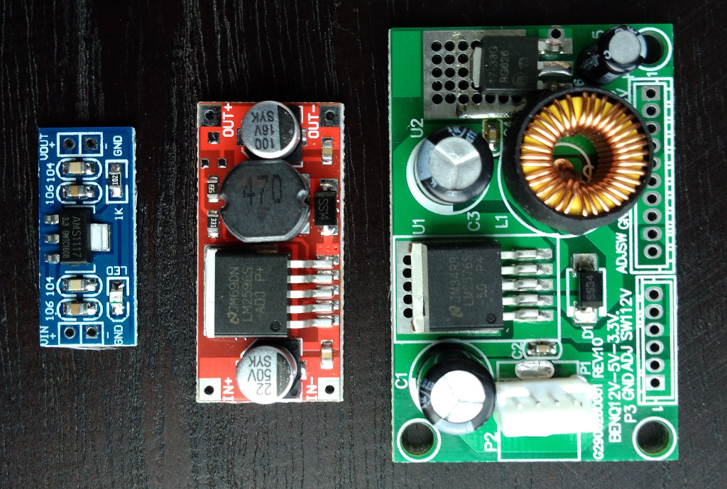
Tiny: ~USD1; *As described by the seller: Input: DC 4.5V--7V (Input Voltage must be Greater than the Output voltage high above 1V.)
out 3.3V
Boots but keeps restarting.
With a 870 uF at the output:
in 5V: boot time 170-190mA, stable: 170-180mA
Mid-sized: ~USD1.8; As described by the seller: 10W DC Buck Step Down Regulator Voltage Power Converter Module 3.6v~40v 2A 3.3v
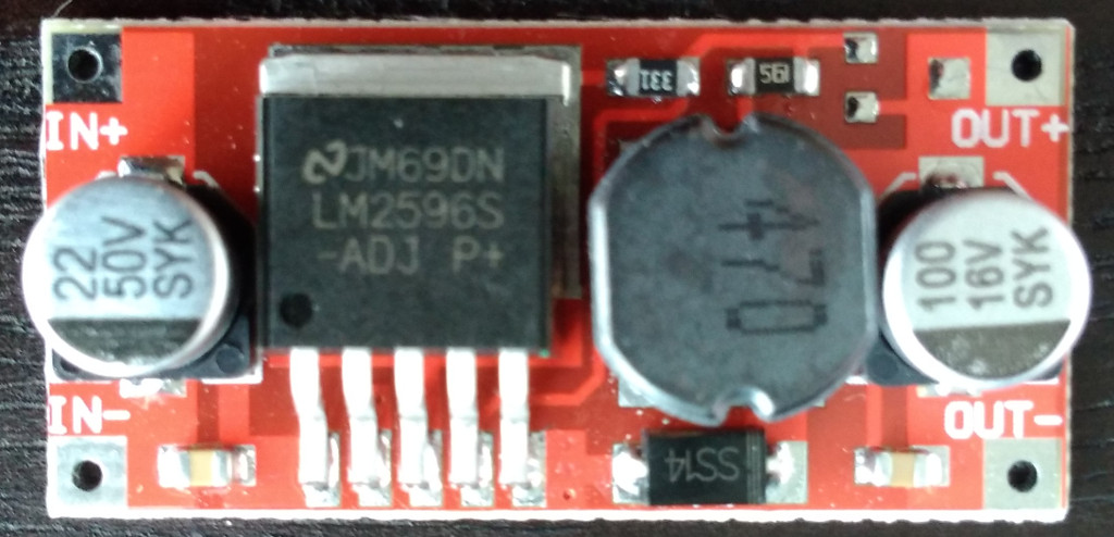 out 3.4V
in 5V: boot time 140-230mA, stable: 165-185mA
in 12V: boot time 40-75mA, stable: 70-75mA
The big one (5V and 3.3V): ~USD2.75; As described by the seller: DC-DC 12V To 5V 3.3V Step-down Power Supply Module, max 3A.
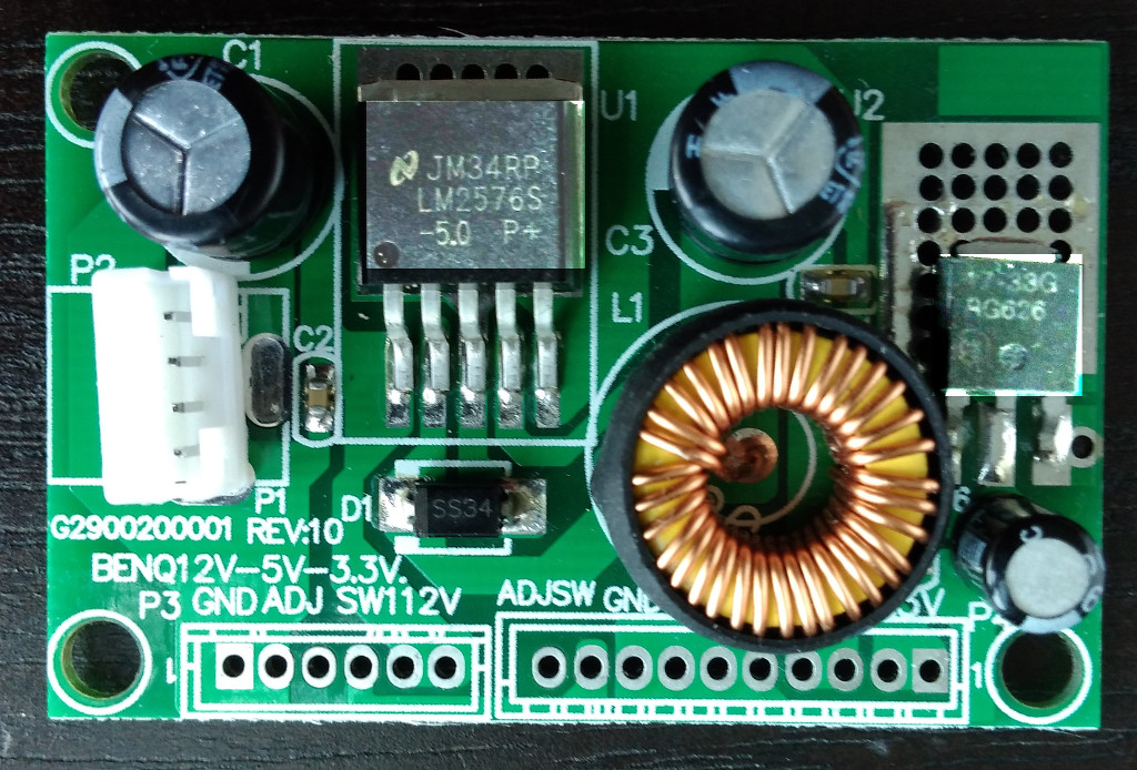
out 3.3V
in 5V: doesn't boot
in 12V: boot time 70-130mA, stable: 100-110mA
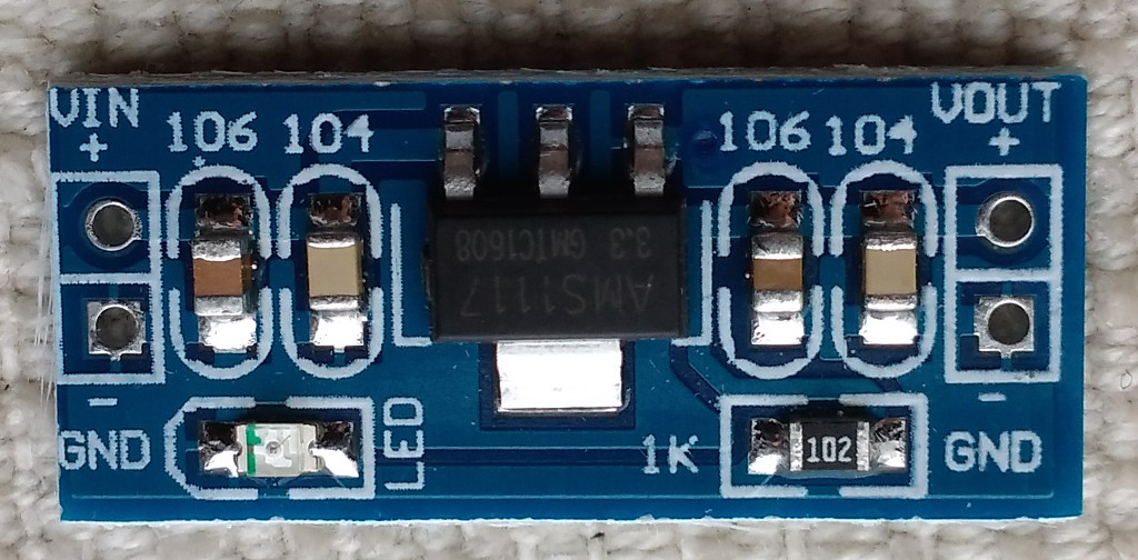
And of course, the advice to add some large capacitors at the output was hitting the nail on the head. The 1117 and its clones make the Omega to boot and work stable with no problems including this 4m poor quality wires. I checked some electrolitic and tantalum capacitors in the range of 800-1000uF.
One more piece of info, I arbitrary limited the current booting with the input of 3.3V, the 2m long 2.3mm conductor and 200-300mA is no go, but 500mA already boots and stays stable (at least for the bare Omega2 used).
Question: is the Vin of 3.4V for the Omages a major concern? I liked the middle-sized converter but this is also the only with the Vout out of range (for both 5V and 12V Vin).