Omega 2/2+ Without Any Dock
-
@Costas-Costas said in Omega 2/2+ Without Any Dock:
@fossette do you think $15 is a reasonable price for the bare minimum dock?
That's irrelevant! There are lots of hardware offerings out there. You have to choose a product with your best judgment. Some people are even doing a dock on their own, just because they can.
-
@fossette just canvassing your opinion. As requested I have edited my post.
Anyone want to buy a new laptop for $200 and the case for the laptop is a snip at just $600
")
-
@WereCatf thank you for suggestions. I will examine more.
@Joni-Korhonen I didn't even try with LM317 since I am not sure how to use it. If you have any suggestions(maybe schematics) I'd like to use it.
@Costas-Costas I totally agree with you. I find it expensive. Maybe not others but I do. It would be nicer to build my own dock if possible. Do you have any suggestion you liked?
-
Not tried any of the PCB's but you might want to take a look at:
https://community.onion.io/topic/1338/new-omega2-basic-shield-power-ftdi-i2c-and-spi
and
https://community.onion.io/topic/1094/diy-onion-mini-dock
-
@Costas-Costas looks really nice. I am trying to find out how to understand the pieces on the shield.
-
@Gökhan-Türkeli OK, I can put an example of my setup, if needed (when back at home). I used this calculator to calculate correct resistor values.
l317calc That link also shows the pins of 317. to vin you connect + from your power source and ground is common.Actually here seems to be an example, which is almost like mine (I have omitted the capcitors on output, but it can be good to have there also):Example
-
So, what people are saying in more "google friendly terms" are that the Omega2/2+ Single Board Computer (SBC) module does not fit into a standard board with 0.1" (2.54mm) spaced "tie points" --or more affectionately "holes".
The Omega2/2+ uses a 2mm pitch similar to the Xbee wireless arduino module.
That is all fine and dandy, how to I get pins into my breadboard without spending $15 on a shield?
https://www.amazon.com/gp/product/B0143YRONY
So, the other concern is that the 2mm pins are shorter and thinner than a "regular" pin. The cable above does grip on the pins. There is a caveat. You cannot hook up every pin with the cable above. You can hook up three sets in a row. I also turned a jumper wire pair sideways 90 degrees to hook up one pin by itself ( terrible ascii art... |oo|oo|x|8|x|oo|oo| where the top of the "8" is not connected to any pin and pins 5 & 7 of this diagram are not connected to anything ).
Literally, you cannot connect all the pins with the ribbon cable jumper wires which is sadness-- but I've been able to get all the ones I've needed with them so far.
It would be nice if Onion sold a reasonably priced 2mm --> 2.54mm converter cable or some kind of socket converter to allow breadboard plugging. Specifically something basic that just offers pin connectivity...
My 2 cents for what it is worth...
-
Excellent post @Brad-Chesney
-
I'm not done yet...
So, now I've got pin connectivity and I need power and I don't want to muck around with something so basic as isolating 3.3v.
https://www.youtube.com/watch?v=tU0ztOQP6PA2
For other projects to provide power I have used the "breadboard power supply" in this video. They are made by many brands in this configuration, I don't know that there is much different between them.
It also works for suppling power to my Omega 2+. The USB port puts out 5V. The 2x4 header in the middle also puts out power. 2 pins on one side are +5v, two pins on the same side are +3.3v, and the 4 remaining pins all in a row are grounds or the negatives. They are marked. Then additionally the pins at the edges that insert into the breadboard power rails can be set via jumper to either a 5v or 3.3v voltage differential to ground.
With a 5v DC power supply I was unable to get proper voltage out of the regulators. I have been using a 9v DC power supply which has yielded power output that isn't perfectly at 5v or 3.3v output but it is close enough and within tolerances.
I bought my "breadboard power supply" off of ebay for a pittance and I am very satisfied with the purchase.
The Omega 2+ uses 3.3v+ and ground- and powered up nicely.
And that is the completion of my adventures in cheapskate IoT in respect to getting it up and running so I could start trading time for fun with the Omega 2+.
Now to get sound input and output working for voice controls to maybe hook up the IBM Watson or Alexa APIs...
-
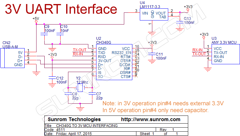
I am planning to create my own custom dock. Instead of CP2102 USB to serial converter, I am planning to user CH340G which is easy to solder. For power supply, I am planning to user AMS1117 since I assume that Omega2 does not require more than 300mA. I notice that in the schematic, the voltage divider is used between PC_TXD and RXD. Is it to reduce the 5V to 3.3V? I am planning to use CH340G with 3.3V power supply. Something like this. If do so, should I use the voltage divider network? I assume that I don't have to use. Will post the schematic for the review once I complete.