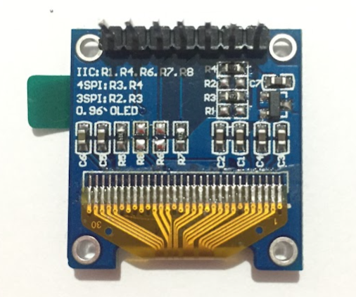
I was able to solve it and since I haven't seen this online anywhere, I think it might be helpful to explain it here. Turns out, that the model of SSD1306 I'm using comes with three operation modes: I2C, 3-wire SPI and 4-wire SPI. By default, 4-wire SPI is used, however, it comes with what I think is a pull-up resistor marked as R6 for the I2C mode, which also serves as the MOSI pin for the 4-wire SPI mode. I desoldered R6 as shown in the attached image and now the Omega2+ boots with no problem and I was able to use the display using Blinka and the python driver from Adafruit.
