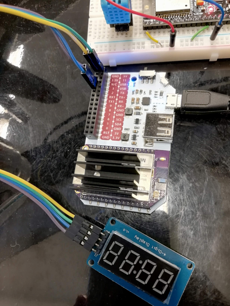
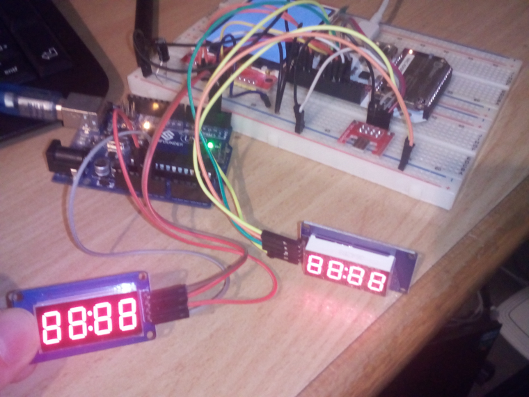
[need help] bought a 4 bits digital LED module
-
@unique1984 thanks for the video, quite length full, but I will watch it. it looks to be a good start!
-
Greetings,
After working on for a few days and nights, I still don't get it.. I really sucks and noob. the concept of just switching the GPIO's is quite hard. I looked into the given libs to get some clue, but not progress.
this is the rough code that I got.
import time
import onionGpio

clk = 2
dio = 3

# gpioNum = 2
# gpioObj = onionGpio.OnionGpio(gpioNum)

clkObj = onionGpio.OnionGpio(clk)
dioObj = onionGpio.OnionGpio(dio)

clkObj.setOutputDirection(0)
dioObj.setOutputDirection(0)

## set to output
# status  = gpioObj.setOutputDirection(0)

## alternate the value
loop    = 1
value   = 1
while loop == 1:
    # clkObj.setOutputDirection(value)
    # dioObj.setOutputDirection(value)

    # reverse the value
    if value == 0:
        value = 1
    else:
        value = 1


    # set the new value
    # status  = gpioObj.setValue(value)
    # print 'GPIO%d set to: %d'%(gpioNum, value)

    print 'GPIO%d set to: %d val: %d %d'%(clk, clkObj.setValue(value), value, int(clkObj.getValue()))
    print 'GPIO%d set to: %d val: %d %d'%(dio, dioObj.setValue(value), value, int(clkObj.getValue()))


    time.sleep(5)
maybe programming web Softwares/Programs is different from here.. from that simple loop, something should happen, but I don't get anything.. I'm better of building web servers from golang/rust and crosscompile it to mips..
anyway, probably I can't just get this in a few days. will try to learn more from the internet.
-
@jeane-soliva Porting the above libraries should be fairly easy with just
onionGpio. Only thing I'm worried about if the chip has some very strict timing requirements, like e.g. a constant fairly high data rate, but I'll see. I'll port the library blind without having the chip, you can test it then.
-
こんにちは、honestly, I don't know how to thank you. if you can port that library, and doing something like
display.setSegment()would really contribute a big value and great help among others too.. and I would be gladly to help testing it. this is my github if you plan to share it on github, invite me. thank you!
-
@jeane-soliva @Maximilian-Gerhardt I hope these links will help you too:
A C library for controlling Titan Micro Electronic's 7-segment LED controllerseeed
Grove - 4-Digit Display
-
@Maximilian-Gerhardt got your repository, thanks! give me some few time to sort building the mips toolchain.. hopefully, my build will succeed.
@György-Farkas thanks for the tip!
-
We're working on it on https://github.com/maxgerhardt/omega2-tm1637. So far, the first C++ version was written, untested. Test und Python version upcoming.
-
@Maximilian-Gerhardt sorry for the long wait. I had some problems building the toolchain. anyway, after editing some environment variables from your makefile, tried building your repo, and compiling it successfully I guess.
$ make
mipsel-openwrt-linux-g++ -o tm1637_example_display -O3 -ggdb -g -Wall -Wextra -std=c++14 -I /home/docker-user/omega/source/staging_dir/target-mipsel_24kc_musl-1.1.16/usr/include -I /home/docker-user/omega/omega2-tm1637/omega_includes -L /home/docker-user/omega/source/staging_dir/target-mipsel_24kc_musl-1.1.16/usr/lib -L /home/docker-user/omega/omega2-tm1637/omega_libs -L. example_display.cpp TM1637.cpp Arduino.cpp  -loniondebug -lugpio
In file included from Arduino.cpp:3:0:
/home/docker-user/omega/omega2-tm1637/omega_includes/ugpio.h:57:39: warning: unused parameter 'gpio' [-Wunused-parameter]
 inline int gpio_is_valid(unsigned int gpio)
                                       ^
/home/docker-user/omega/omega2-tm1637/omega_includes/ugpio.h:73:39: warning: unused parameter 'gpio' [-Wunused-parameter]
 inline int gpio_cansleep(unsigned int gpio)
then after scp'ing to my omega, then running it.
Beginning to test program
> exporting gpio 8
> setting to input
> exporting gpio 9
> setting to input
> setting to input
> setting to input
> setting to input
> setting to input
> setting to input
t
Goodbye
unfortunately, there is nothing displayed..
btw, does
        uint8_t pinClk = 18;
        uint8_t pinData = 19;
needs to be 18 and 19? I don't have that.. I am using a power dock 1, not 2.. tried changing it to other GPIO, but still not working..
-
Tomorrow I'll have the real hardware and test and debug it. Could be a timing issue. Would have been a wonder if it worked on the first try anyways.
The GPIOs can be arbitrary. VCC and GND of the module have to always go to 3.3V and GND though.
I don't find a reference to Power Dock 1.. What pins are available there? But you are testing this on an Omega2, right?
-
@Maximilian-Gerhardt thanks! tried quick hacking the library, but no work.. my knowledge of writing data for this is still limited..
I am pretty sure I am using the correct device..

and the dock is this from that image, mine is quite different, the layout is different from the expansion.. I dont know why. don't have pins 21/20
-
You have VCC on +5V, but all the logic is on the Omega2 is 3.3V and the display module must also get 3.3V. That hopefully shouldn't have damaged the module or your Omega.. I'll see when I get the hardware

Edit: Hardware just arrived. Working on this this evening.
-
Found the bug. My Arduino abstraction layer was setting the pin to HIGH after it was initialized as OUTPUT pin, while the actual Arduino implementation sets it LOW. This is also what the code expects.
Changing
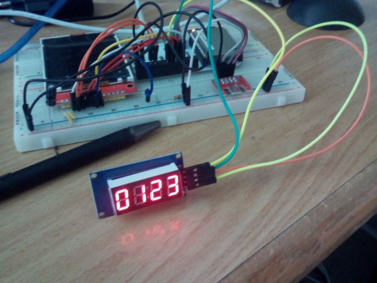
gpio_direction_output(pin, HIGH)togpio_direction_output(pin, LOW)inpinMode()gives you the same result as on an Arduino Uno: (Test code activates all segments)
Fix and more description will be in the repo soon. Now I should be able to write a python version.
-
@Maximilian-Gerhardt awesome!! Fantastic job! I am glad it's working on to you.
-
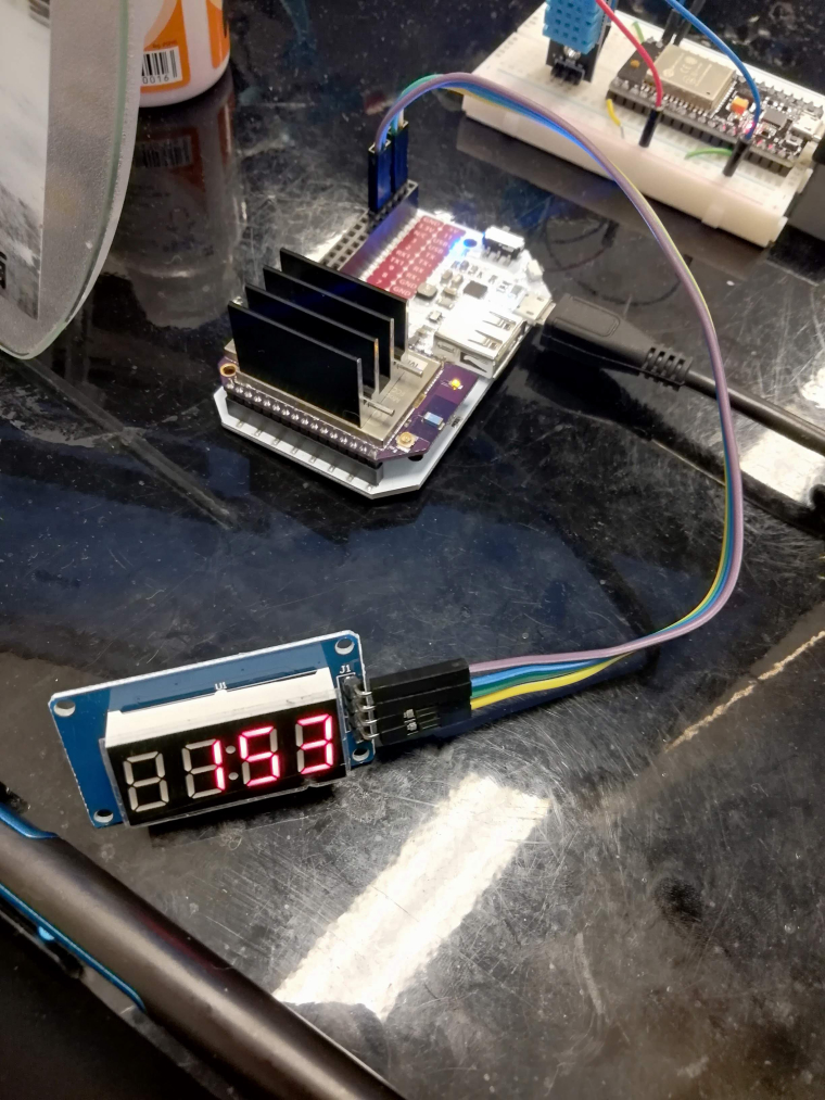
damn got it now! finally. this is the sample code I got.
after setting
HIGHtoLOWinpinMode()ofArduino.cpp} else if (mode == OUTPUT) { if ((rv = gpio_direction_output(pin, LOW)) < 0) { perror("gpio_direction_input"); } }#include <stdio.h> #include <stdlib.h> #include <unistd.h> #include "TM1637.h" int main() { int k; printf("Beginning to test program\n"); uint8_t pinClk = 2; uint8_t pinData = 3; TM1637Display display(pinClk, pinData); uint8_t data[] = { 0xff, 0xff, 0xff, 0xff }; display.setBrightness(0x0f); display.showNumberDec(153, false, 3, 1); sleep(2); printf("Goodbye\n"); return 0; }
-
Repository was updated with a fixed version and better demo -- now the Python versions is coming.
-
-
@Maximilian-Gerhardt this should be added in the examples! looks amazing! thank you!
-
I connect Omega2 lte to "IOT" at T-Mobile with special SIM. I installed client openvpn machine and connection works with portal and get IP address . The omega2 lte makes only a connection to client if I enter terminal command "lted" ,It connects and gets IP . client can ping omega2 LTE. Command "lted"in terminal isn''t closed. Entering CNTR-C I get cursor back, but the connection via LTE shuts down. What Do I wrong or what is not correct configured```

-
@kottes Please create a new thread for this question, this thread is 3 years old. I'll answer on the new thread.
