@Morten-Gustafsson Not particular sure if this will helped but there are few alternatives
- You can use bluetooth to communicate between the 2 Omega2 (depending on how far they are)
- You can use cloud messaging service like pubnub
@Morten-Gustafsson Not particular sure if this will helped but there are few alternatives
@Guillaume-Langelier this sounds interesting. Can you give use case example at how you expect it to work or how the user will use it ?
Bought the female and male pin header from Aliexpress that is compatible with Omega 1 in case anyone is interested.
https://www.aliexpress.com/item/10PCS-2mm-40-Pin-Male-Single-Row-Pin-Header-Strip/32698646012.html
https://www.aliexpress.com/item/10PCS-LOT-Female-Pin-Header-Strip-1-40-Pin-2mm-Single-Row-Female-Pin-Header/32625294731.html
@Fred-Blais said in Omega compatible 2.00mm female pin headers:
There is also ebay. Look for these items:
10 Pcs 2mm Pitch 16 Pin Female Single Row Straight Pin Header Strip
20Pcs 2mm 2.0mm Pitch 1x16 Pin 16 Pin Single Row Straight Female Header Strip
Has anyone bought the SMD version of the right-angle header pins off from eBay or Aliexpress before ?
Thanks
@Luciano-S. said in Expansion Dock Header Pin:
Did you see this?
http://community.onion.io/topic/980/omega-compatible-2-00mm-female-pin-headers/7
Thanks that reallly help
Hi,
I'm looking at the mechanical drawing of the expansion dock https://github.com/OnionIoT/Onion-Hardware/blob/master/Schematics/Omega-Expansion-Dock.pdf and was wondering if anyone know where can I get more information about the specification of the header pins ?
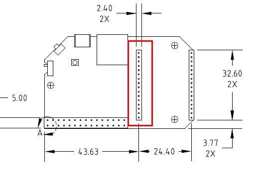
Thanks
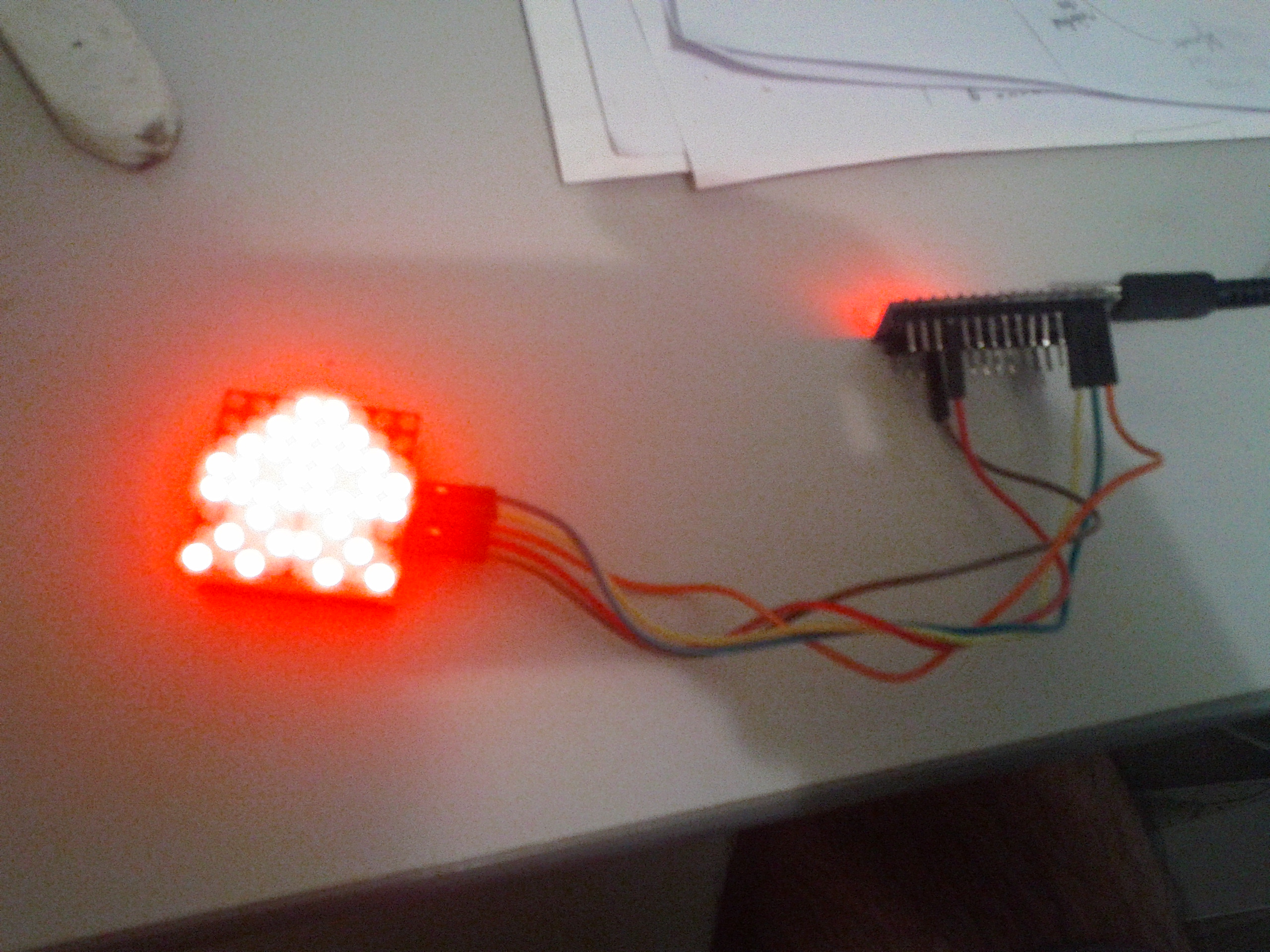
After reading the datasheet looks like I'm using the wrong decode mode. Here are the steps in case anyone is having the same problem
Following is the wiring

Following is the test bash script
#!/bin/sh
#set power ON
spi-tool -b 0 -d 1 write 0x0C 0x1

#set scan limit
spi-tool -b 0 -d 1 write 0x0B 0x0f

#decode mode
spi-tool -b 0 -d 1 write 0x09 0x01


#Set each display in use to blank
for i in 1 2 3 4 5 6 7 8 9
do
  spi-tool -b 0 -d 1 write 0x$i 0x0
done

for i in 1 2 3 4 5 6 7 8
do
  spi-tool -b 0 -d 1 write 0x$i 0x11
done

sleep 1

for j in 0x11 0x22 0x33 0x44 0x55 0x66 0x77 0x88 0x99 0xAA 0xBB 0xCC 0xDD 0xEE 0xFF
 do
  for i in 1 2 3 4 5 6 7 8
  do
    spi-tool -b 0 -d 1 write 0x$i $j
  done
  sleep 1
 done
Hi,
Thought I move my previous question in different topic and share the finding here.
So I bought a MAX7219 and was playing around with the spi-tool. Looking at Arduino code and also 7219 datasheet able to do the following
// set scan limit
spi-tool -b 0 -d 1 write 0x0B 0x0f
// set power ON
spi-tool -b 0 -d 1 write 0x0C 0x1
// decode mode
spi-tool -b 0 -d 1 write 0x09 0xFF
// test mode
spi-tool -b 0 -d 1 write 0x0F 0x1
with the test mode (0x0F) able to turn on all the LED and to turn of use 0x0 for 0x0F register.
But the funny thing is when I use the write command to write on the first row like so
spi-tool -b 0 -d 1 write 0x00 0x01
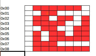
I see 2 LED turned on in Row 0 which is not right. I'm attaching diagram of which LED turn on when using the following command
spi-tool -b 0 -d 1 write 0x00 <value>
Any idea why the LED is not turn on properly ?
Tested in Arduino and all works fine. I tested with Arduino using the sample code from here https://brainy-bits.com/tutorials/how-to-control-max7219-led-matrix/
Seems like the issue is with the mounting of the filesystem. Found the fix via this blog https://drewsymo.com/2016/05/09/fixing-error-writing-fstab-read-only-file-system-2/
How come the wiki page does not include instruction to remount / so we can edit the fstab file ?
Able to mount the USB as /overlay now
Filesystem 1K-blocks Used Available Use% Mounted on
rootfs 7560360 38800 7114472 1% /
/dev/root 7680 7680 0 100% /rom
tmpfs 30576 500 30076 2% /tmp
/dev/sda1 7560360 38800 7114472 1% /overlay
overlayfs:/overlay 7560360 38800 7114472 1% /
tmpfs 512 0 512 0% /dev
Hi,
Trying to extend the /overlay using the following tutorial https://wiki.onion.io/Tutorials/Using-USB-Storage-as-Rootfs but I'm getting error when editing the fstab file as follows
root@Omega-09DB:/# block detect > /etc/config/fstab
/bin/ash: can't create /etc/config/fstab: Read-only file system
Any idea ?
Thanks
@Kit-Bishop said in RGB Linux Kernel Code:
Some sample code for driving the MAX7219 from the Arduino can be found at
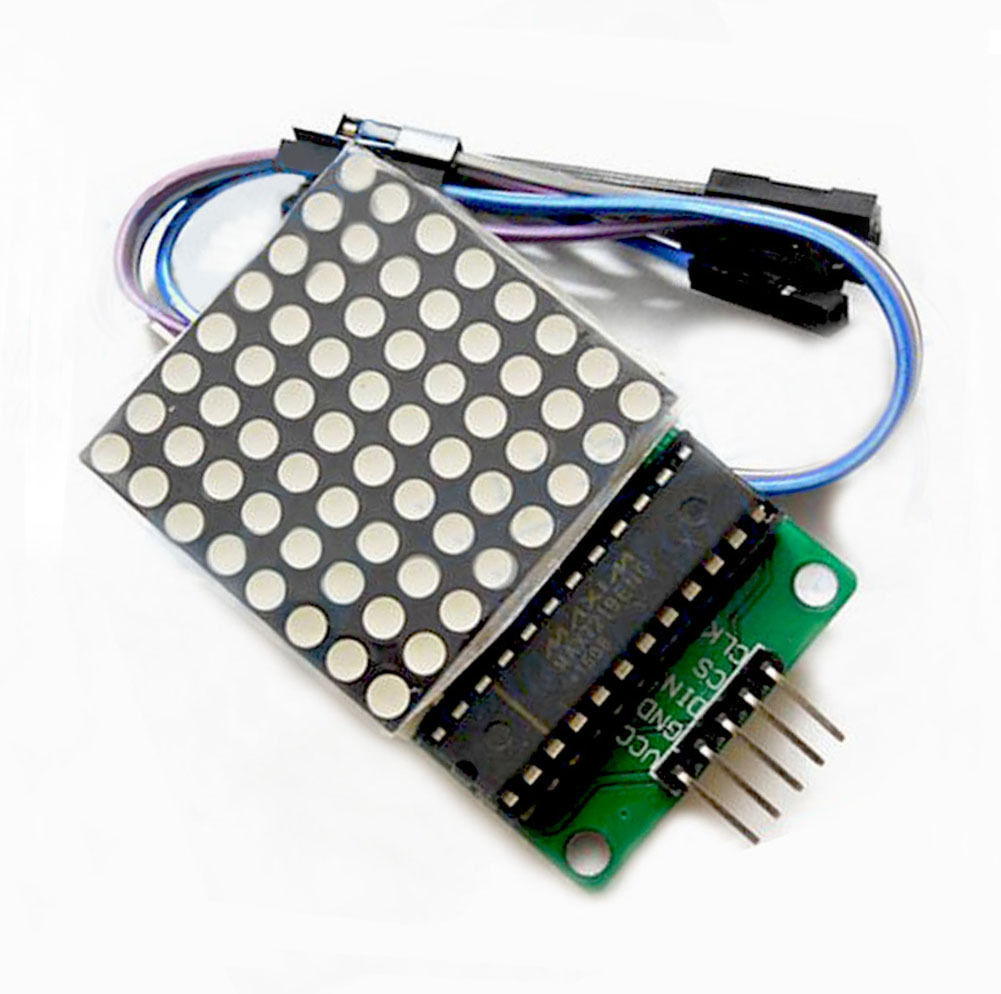
@Kit-Bishop just bought this MAX7219EWG module and was able to drive it using Arduino (using the LedControl library). Now planning to play around with it using your library. Need help to check if the below table wiring is correct (not sure about the CS)
LED Matrix <----> Omega
VCC <---> 5V
GND <----> GND
DIN <-----> 6
CLK <-----> 7
CS <-----> ??
I found the problem. Seems like the file that was created initially by Onion Webapp has all zeroes inside it. The property step was to hit the 'Save to Omega' button to save the actual content into the file.
After doing that I was able to show the image.
Thanks for listening 
Hi,
I bought 0.96" I2C display and able to use oled-exp app to write to the screen. I've also managed to use the console app to upload image and get it converted to .lcd format.
When I use Onion WebApp I can see the image drawn in the OLED but when I use the same .lcd file with oled-exp using the following command
oled-exp draw /root/image.lcd
it just make the OLED blank (black) and nothing show up.
Any idea ?
Thanks
@Kit-Bishop sorry yeah you are right is' the MAX7219 (late night coding is not helping with the hand and eye co-ordination) 
Will check the Arduino code and experiment with it. Thanks
@Kit-Bishop went through the code and I have a question regarding the shiftOut (..) function inside GPIOAccess.cpp can this function be used to drive like the MAX7129 LED matrix.?
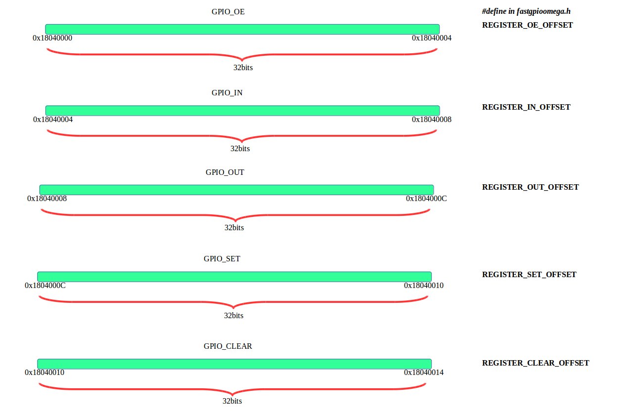
Thought I share the diagram I created to make it easier for me to learn the GPIO registers as most of the time will be using GPIO pins to control external 'thing'.
Sorry didn't realise the SoC datasheet was made available https://wiki.onion.io/Documentation/Hardware/ar9331_datasheet.pdf
Found an interesting wiki page comparing speed between setting GPIO via sysfs and register http://www.unwireddevices.com/wiki/index.php/Working_with_GPIOs_(C/C%2B%2B)
Looking at fast-gpio code the way it is controlling the RGB is using register defined in fastgpioomega.h
#define REGISTER_BLOCK_ADDR 0x18040000
#define REGISTER_BLOCK_SIZE 0x30
is the datasheet available for the SoC to learn more about the available registers ?
Thanks