Help getting Ethernet configuration correct [resolved]
-
Okay so the fact that there is no voltage at Omega2+ Pin #25 NET_POW is normal - got it.
The Ethernet doc schematic does show that it has the RX and TX center taps tied to ground through a 49.9 ohm resistor and 100 nf cap.
So that should all be physically wired correctly.
certainly the Ethernet Dock wouldn't be sold if it didn't work so it seems that this has to be a configuration issue right?
-
Finally got time to wire it up.
Electrically, it is working. However, if I have both WiFi and Ethernet plugged in at the same time during booting,
neither WiFi nor Ethernet will get IP address assigned by my (same) home cable router.
If I unplugged the Ethernet cable then boot, just by WiFi itself, WiFi will acquire an IP address (e.g., 192.168.10.10.)
I can then plug in the Ethernet cable and use web interface thru Terminal to assign it an IP address;
e.g., ifconfig eth0 192.168.10.20. It will be fine either way to connect to my home network.I did not spend any time to troubleshoot. Just to validate the circuitry.
ccs_hello
-
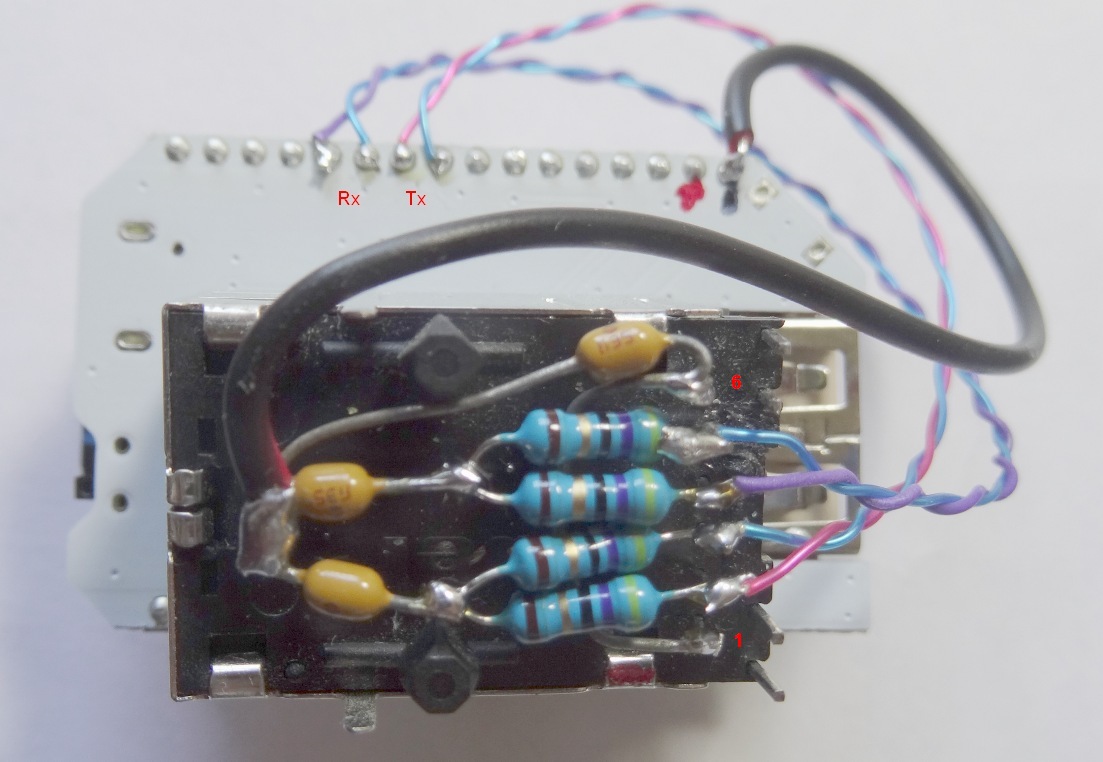
BTW, my specific brand of Ethernet magnetics (a.k.a. EasyJack) is Bel 0810-1XX1-02.
Pin 1: Tx C.T., 2: Tx+, 3 Tx-, 4 Rx+, 5 Rx-, and 6 Rx C.T.Pin 1 and 6 tied together then thru 100nF to Gnd.
Pin 2 and 3 each thru 50 Ohm termination resistors to reach a 100nF capacitor. 100nF's other end tied to Gnd.
Pin 4 and 5 each thru 50 Ohm termination resistors to reach a 100nF capacitor. 100nF's other end tied to Gnd.P.S. a low cost method is to buy a "HLK-RM04 Test Board". It's approx. $5 shipped and has a few parts to be re- purposed.
See https://www.aliexpress.com/item/Free-Shipping-Uart-WIFI-module-serial-ports-WIFI-MCU-WIFI-HLK-RM04-SCM-wifi-test-board/729142578.html or http://www.ebay.com/itm/HLK-RM04-UART-to-WIFI-Serial-Port-to-Wifi-Module-Test-Base-Board-/112318260620ccs_hello
-
That was it. My mistake was I had the center tap to Vcc through .1uf Cap instead of to ground.
I thought I saw it to Vcc in schematics... Oh well, thank you very much!
I am able to use ethernet as bridge now with default firmware config or as ethernet client with my initial config.
-
@ccs-hello Do you connect then directly Tx+ and Tx- to the pins with the same name on your Omega2 (same for Rx+ or Rx-) or you rather use a cross-over?
According to the Ethernet expansion dock schematic, it should be crossed-over, but my logic dictates me it should be straight (that is: TX+- on Omega2 to wires 1 and 2 on the eth cable, RX+- to wires 3 and 6 on the eth cable).I have made my own Ethernet expansion board on which I have placed an Ethernet switch, so that I can have more than 1 Phy. I have connected it straight there and it works perfectly. I must also mention that the switch is Auto-MDIX capable. Now I want to design a smaller version of my Ethernet expansion board (without the switch) and I really have doubt about how to connect the pins.
-
It is a straight through connection.
-
@Jeff-Seese Not on the Ethernet shield from Onion: they connect omega2 pins Tx+ and Tx- to eth cable pins 3 and 6 and Rx+ and Rx- to 1 and 2.
-
No cross-over.
Omega2's Tx pair goes to Ethernet magnetic's TX leads
and O's RX to magnetic's Rx.ccs_hello
-
@ccs-hello Thanks for the replies, but sorry to insist. This is the Ethernet Expansion Dock schematic:
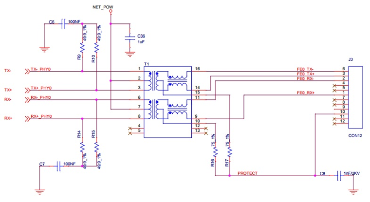
As you can see, TX+ and TX- are connected to the pair 3-6 on the cable. Rx+ and Rx- are connected to 1-2. This is what I dont get. Shouldn't it be the other way around?
-
I saw that Omega 1 schematic diagram before.
It was a surprise since it's different than all those Ethernet MagicJack's diagrams from several mfgs. The standard design is Tx out goes to RJ45's pin 1/2 (the Tx pair) and Rx out goes to 3/6 (Rx) pair.Guess the diagram you've cited is built for "naturally cross-over" for unknown reasons.
ccs_hello