How to switch AGPIO (GPIO 18/19) - Omega2 FW vs LEDE build
-
@WereCatf The fix just makes "pwm0" group GPIO by default (which I agree should be the case, too). But this does not help with AGPIO mode set.
@Lazar-Demin yes, I realized that GPIO18/19 were in PWM mode by default. I fixed this in my experimental DTS already.
However that's not what I was talking about. There is a global switch for all EPHY port1..4 pins to make them either digital I/O functions (GPIOs, PWM, etc.) or ethernet differential "analog" TX/RX pins.
The bits called EPHY_GPIO_AIO_EN, bit 20..17 in AGPIO_CFG (0x1000003C) control that mode, as I explained in the original post. After a hardware reset, these bits are set to 1, so the MT7688 starts up in digital (GPIO) mode for these pins.
My problem is that I can't figure out why my LEDE build at some point switches these pins to Ethernet.
As it's not in the device tree, it must be some network related driver/package doing this, only I can't find it. If I had the omega2 .config, I would diff it with mine and probably be able to spot the difference.
-
@luz I don't understand the problem. GPIO18 and GPIO19 work fine with my latest change, I can see the pin-state change when I connect the pin to HIGH or LOW.
-
@Lazar-Demin said in How to switch AGPIO (GPIO 18/19) - Omega2 FW vs LEDE build:
Also, we've open-sourced
omega2-ctrl, check it out here: https://github.com/OnionIoT/omega2-ctrlGreat! Thanks a lot!
This allowed me to figure out what the "ephy" setting that confused me actually is.
It controls EPHY_LED0_N_JTDO pin to be either GPIO43 or the Ethernet LED for Port 0 (P0_LED_AN_MODE, Bits 3..2 in GPIO2_MODE). Thus, it should probably be called "eled". On the other hand, as that pin seems not connected in the Omega2, maybe it should be removed from omega2-ctrl, together with "wled" which seems not connected, too.
-
@WereCatf said in How to switch AGPIO (GPIO 18/19) - Omega2 FW vs LEDE build:
@luz I don't understand the problem. GPIO18 and GPIO19 work fine with my latest change, I can see the pin-state change when I connect the pin to HIGH or LOW.
It's definitely not a .dts thing. If I manually disable the AGPIO (see devmem command in the original post), GPIO18/19 work fine.
But some software piece in my LEDE build does switch this entire pin group (all 16 bins related to ethernet switch port 1..4) into AGPIO/ethernet mode.
In the meantime, I have a suspect: it could be the mere presence of the "swconfig" package. This is a utility to control built-in switch hardware, but it also pulls in a kernel module and maybe this module enables the switch hardware. I'm now building a new image without swconfig, let's see if that helps...
Could you please check in your .config, do you have "swconfig" package selected?
-
@luz I have
CONFIG_PACKAGE_swconfig=ybutCONFIG_PACKAGE_kmod-swconfig=m-- perhaps that's the difference? You could also try if just disabling the switch in the DTS-file works, e.g. add the following to the DTS:&esw { status = "disabled"; };
-
@WereCatf disabling the switch in the device tree kills ethernet functionality entirely

So this is no option for me - I need the ethernet port.
Maybe its using the ethernet port that causes AGPIO to get enabled (and GPIO18/19 disabled)?
Do you have ethernet in use on your omega2?
BTW: CONFIG_PACKAGE_swconfig=y and CONFIG_PACKAGE_kmod-swconfig=m didn't help either.
-
@luz No, I don't have any of the various docks, including the Ethernet-dock.
-
@WereCatf I mean, is the eth0 interface enabled (in software)? It does not matter whether you have a ethernet dock or not.
But if it isn't enabled in your configuration, then that could be the reason why GPIO18/19 work for you, and don't work in my case.
-
@luz It is enabled and all, yes. At least I haven't done anything to disable it.
-
Hi,
Yeah, probably I'm a thread necromancer... But I think I found why (when, how) the official Omega2 image sets AGPIO to digital IO, and which is not done by the original LEDE project.
I did the following trick, and it seems it succeeded: I connect one channel of my scope to one of the GPIOs (
GPIO17) which was ~1.65V by default during boot and changed to 0V at a point in time and I attached the other probe to the TX line.As it clearly show the next screenshot, the line switched to digital at SD card initialization:
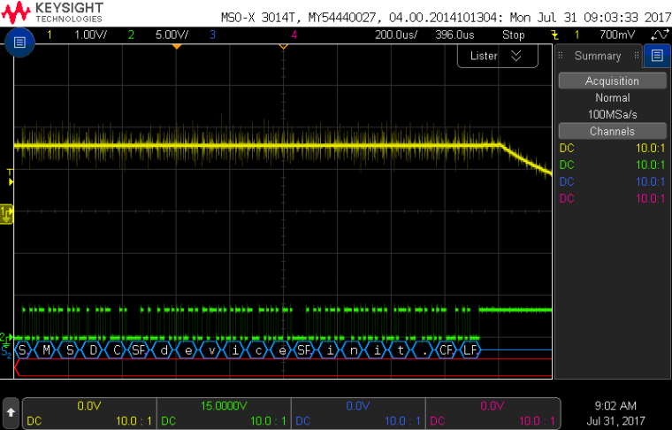
It changes right after the kernel prints
MSDC device init.. So, I searched for it in the kernel source and I found.Here is the corresponding snippet (it is located in
linux-4.9.37/drivers/mmc/host/mtk-mmc/sd.cstatic int __init mt_msdc_init(void) { int ret; /* +++ by chhung */ u32 reg; #if defined (CONFIG_MTD_ANY_RALINK) extern int ra_check_flash_type(void); if(ra_check_flash_type() == 2) { /* NAND */ printk("%s: !!!!! SDXC Module Initialize Fail !!!!!", __func__); return 0; } #endif printk("MTK MSDC device init.\n"); mtk_sd_device.dev.platform_data = &msdclinux-4.9.37/drivers/mmc/host/mtk-mmc/sd.c0_hw; if (ralink_soc == MT762X_SOC_MT7620A || ralink_soc == MT762X_SOC_MT7621AT) { //#if defined (CONFIG_RALINK_MT7620) || defined (CONFIG_RALINK_MT7621) reg = sdr_read32((volatile u32*)(RALINK_SYSCTL_BASE + 0x60)) & ~(0x3<<18); //#if defined (CONFIG_RALINK_MT7620) if (ralink_soc == MT762X_SOC_MT7620A) reg |= 0x1<<18; //#endif } else { //#elif defined (CONFIG_RALINK_MT7628) /* TODO: maybe omitted when RAether already toggle AGPIO_CFG */ reg = sdr_read32((volatile u32*)(RALINK_SYSCTL_BASE + 0x3c)); reg |= 0x1e << 16; sdr_write32((volatile u32*)(RALINK_SYSCTL_BASE + 0x3c), reg); reg = sdr_read32((volatile u32*)(RALINK_SYSCTL_BASE + 0x60)) & ~(0x3<<10); #if defined (CONFIG_MTK_MMC_EMMC_8BIT) reg |= 0x3<<26 | 0x3<<28 | 0x3<<30; msdc0_hw.data_pins = 8, #endif //#endif } sdr_write32((volatile u32*)(RALINK_SYSCTL_BASE + 0x60), reg); //platform_device_register(&mtk_sd_device); /* end of +++ */ ret = platform_driver_register(&mt_msdc_driver); if (ret) { printk(KERN_ERR DRV_NAME ": Can't register driver"); return ret; } printk(KERN_INFO DRV_NAME ": MediaTek MT6575 MSDC Driver\n"); #if defined (MT6575_SD_DEBUG) msdc_debug_proc_init(); #endif return 0; }It contains the part which actually do the job:
    reg = sdr_read32((volatile u32*)(RALINK_SYSCTL_BASE + 0x3c));
    reg |= 0x1e << 16;
    sdr_write32((volatile u32*)(RALINK_SYSCTL_BASE + 0x3c), reg);
It sets all the four bits of
AGPIO_CFG(EPHY_GPIO_AIO_EN, bit 20..17 (GPIO14,GPIO15,GPIO16andGPIO17)) to1- thus enabling them as digital GPIO.So, it does not happen in any user space utility (like
swconfig), but it happens in the kernel by enabling SD card.Hope this is still useful for some of you
")
/sza2
-
@sza2-sza2 wow! Impressive analysis and I admire your patience to figure that out!
Indeed, that is useful to know. Technically I had „solved“ the problem with directly writing to the AGPIO_CFG register, but I was wary of that hack without knowing why this was needed in the first place. Now I feel better
LEDE is a router box OS, so it makes sense it makes the choice for Ethernet (AGPIO) by default. But still, it has to make that choice at some point, because after reset, the MT7688 is not in AGPIO mode. So there must be code somewhere else which enabkes AGPIO mode on in the first place. Probably low level ethernet init code...
IMHO it would make sense for a non-router device like the Omega2 to never ever switch these pins to AGPIO, because otherwise there's a short period of unpredictable signal level left between reset and the time whatever code has a chance to switch back to GPIO mode, making them unusable for some purposes.
Your work motivates me to dig in a bit and find (and eventually patch) that initialisation code
")
-
@luz Hi,
I cannot recall perfectly, but as far as I remember, those pins became ~1.65V during bootloader time. Actually, I saw a glitch on the line somewhere before it permanently set to 0V, and it was already during kernel boot (maybe around MTD initialization) but I did not dig deeper. Probably, later on I'll check it - although my online radio receiver already works, so there is no compelling reason
/sza2
-
@sza2-sza2 thinking about it, it is likely AGPIO is enabled in the bootloader already. Onion's modified uboot for sure can use the ethernet, and probably that code was originally written for router-type boxes with all ethernet ports enabled.
Unfortunately, as per now, we don't have the Omega uboot source, so no way to check or even patch. But I hope this is only a matter of time, as it was for the LEDE treewhich is finally available now! (Update 2017-10-07: bootloader sources are available now as well)
-
@luz Hi,
Finally, I had some time to capture the boot process.
GPIO17andUART TXlines were connected to Saleae Logic's inputs. I recorded the waveform from issuing the reboot command on previously booted system, through U-boot, until the next kernel boot (official Omega2 image).Since I was not able to upload the captured file to this comment (although the zipped file was smaller than the 2MB limit), I put in on my Google Drive: omega2_boot.logicdata - if any of you interested in.
There are three spot where
GPIO17changes its state:In U-boot at
Resetting MT7628 PHY:
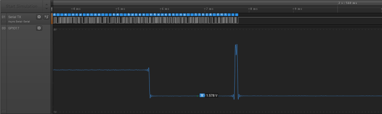
Where it is switched to Ethernet (there is a short period when it seems to configured as GPIO output (for ~70us)).During kernel boot around MTD partitions check:
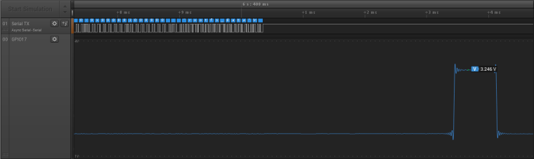
This takes ~700us.And finally, SD init set those pins to normal GPIOs as I figured it out previously:
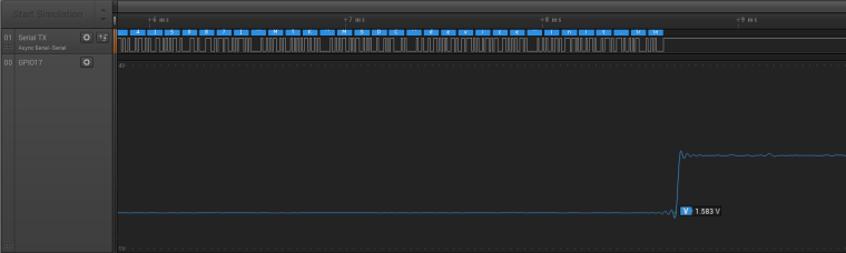
There are three voltage levels:
- ~2.5V (I assume this is when the pin is GPIO input and the logic analyzer pulls somewhat down the pin)
- ~1.5V (when the pin is configured for Ethernet)
- ~3.3V (probably the pin is configured as GPIO output)
So, based on the above, I suppose, it is proven that U-boot changes the state from normal GPIO to Ethernet.
/sza2
-
@sza2-sza2 Your analysis is correct, the problem affects pin 14 through 29, and is easily fixed is in the bootloader:
diff --git a/drivers/rt2880_eth.c b/drivers/rt2880_eth.c
index 7c83a46..9b6f1ec 100644
--- a/drivers/rt2880_eth.c
+++ b/drivers/rt2880_eth.c
@@ -2134,6 +2134,8 @@ void rt305x_esw_init(void)
 /*TODO: Init MT7628 ASIC PHY HERE*/
        i = RALINK_REG(RT2880_AGPIOCFG_REG);
        i = i & ~(MT7628_EPHY_EN);
+       // only enable PHY 0
+       i = i | (0x1e << 16);
        RALINK_REG(RT2880_AGPIOCFG_REG) = i;

        printf("Resetting MT7628 PHY.\n");
-
@wdu cool, thanks for figuring that out!
@Lazar-Demin that should be fixed in the Omega2 bootloader. Only Phy0 is usable in the Omega2, so it makes no sense to enable Phy1..4 at all. With the Omega2S, the other Phys can be used but still I think the bootloader should only enable the port it actually uses (Phy0) and leave the others in GPIO mode.
-
@luz @wdu Thank you for your analysis and solution for this issue. This thread has served me a great purpose for a similar issue.
I need to use phy0 as WAN, phy1 as LAN and other three phy ports as GPIO pins. When I tried the solution that is mentioned in this thread, it disables all the lan ports (except phy0).
When I need only phy1 to be used as LAN, what is the registry value that I should use?
Following, is the change I tried.
volatile uint32_t *reg = (volatile uint32_t*) (gpio_mmap_reg + 0x3c);
unsigned int v;
v = *reg;
v |= 0x1e << 16;
*(volatile uint32_t*) (reg) = v;
-
@Siddharth-Velappan Unfortunately, it is not possible to switch on phy1..4 individually. Only phy0 can be switched independently; the other 4 always are all in phy or all in GPIO mode.
The
AGPIO_CFGregister layout suggests that there is a separate disable bit for each phy, but that's not the case. See the note in the MT7688 datasheet on page 59 reading "When any bit of bit[20:17] is set to 1, P1 ~ P4 will be swiched to digital PADs together."It seems to me that this is one of the small oversights in the MT7688 that probably happened when MediaTek had to "IoT-ze" a former router chip design (too) quickly. Other examples of this are the SPI not working correctly in full duplex mode and the PWM units that are not connected to DMA...
-
@luz Hello! This topic is very interesting for me! I'm using an omega2s and I wanted to use eth0 and eth1 (with a custom board). I've recompiled the official firmware adding devmem, installed it and ran:
devmem 0x1000003C 32 0x00E001FFNow, the registry has the 'correct' value but the switch isn't working. I've ran:
root@Omega-89C9:~# swconfig dev switch0 show
Global attributes:
	enable_vlan: 0
	alternate_vlan_disable: 0
	bc_storm_protect: 0
	led_frequency: 0
Port 0:
	disable: 0
	doubletag: 1
	untag: 1
	led: 5
	lan: 1
	recv_bad: 0
	recv_good: 845
	tr_bad: 0
	tr_good: 816
	pvid: 0
	link: port:0 link:up speed:100baseT full-duplex
Port 1:
	disable: 0
	doubletag: 1
	untag: 1
	led: 5
	lan: 1
	recv_bad: 0
	recv_good: 0
	tr_bad: 0
	tr_good: 0
	pvid: 0
	link: port:1 link:down
Port 2:
	disable: 0
	doubletag: 1
	untag: 1
	led: 5
	lan: 1
	recv_bad: 0
	recv_good: 0
	tr_bad: 0
	tr_good: 0
	pvid: 0
	link: port:2 link:down
Port 3:
	disable: 0
	doubletag: 1
	untag: 1
	led: 5
	lan: 1
	recv_bad: 0
	recv_good: 0
	tr_bad: 0
	tr_good: 0
	pvid: 0
	link: port:3 link:down
Port 4:
	disable: 0
	doubletag: 1
	untag: 1
	led: 5
	lan: 1
	recv_bad: 0
	recv_good: 0
	tr_bad: 0
	tr_good: 0
	pvid: 0
	link: port:4 link:down
Port 5:
	disable: 1
	doubletag: 1
	untag: 1
	led: ???
	lan: 1
	recv_bad: 0
	recv_good: 0
	tr_bad: 0
	tr_good: 0
	pvid: 0
	link: port:5 link:down
Port 6:
	disable: 0
	doubletag: 1
	untag: 1
	led: ???
	lan: ???
	recv_bad: ???
	recv_good: ???
	tr_bad: ???
	tr_good: ???
	pvid: 0
	link: port:6 link:up speed:1000baseT full-duplex
VLAN 0:
	ports: 0 1 2 3 4 5 6
root@Omega-89C9:~#
but the output is the same as before running
devmemand if I connect an ethernet cable on the second port, I don't see any link. What am I missing? Maybe the custom board is not working properly? Or Do I have to configure something in/etc/config/network? Or withswconfig? Sorry for all these questions but I'm relatively new to omega2 and swconfigThank you so much for your support,
Paolo
-
@Paolo-Ciuffetti it seems that this is related to @Dino-Ciuffetti 's question on another thread, is it?
As you say, I also guess it's a matter of getting
/etc/config/networkright, and understandswconfig. Most probably (but I'm not sure), enabling/disabling the switch is not something that can be done while up and running, but must be set up in the startup sequence.I would try to glean information from existing MT7688 based router's firmware (Minibox V2.0, androegg.de...).