Omega2 GPIO input voltage
-
Hoping someone from the community can clarify, otherwise I'll open a ticket with the Helpdesk.
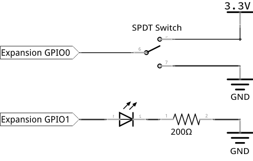
The Omega2 documentation on GPIO's: Using the Omega’s GPIOs is pretty clear that "The Omega2’s GPIOs are not 5V input tolerant!", however the Maker Kit documentation on Reading a Switch provides instruction on building a circuit with 5V input to GPIO0.
So, I'm wondering, is it safe to follow theses instructions in the maker kit?
[edit]
Ok, so the pictures and the text are inconsistent.
While the photos and diagrams show 5V, the text correctly specifies 3.3V:5. Connect the Expansion Dock’s ‘3.3V’ pin to the switch’s top pin.[/edit]
-
@cas this is from the documentation for the expansion dock,
"Your Expansion Dock has a 30 pin Expansion Header, allowing you to use all of your Onion Expansions. The Expansion Dock is powered by the Micro-USB port that supplies 5V to the Dock. This voltage is stepped down to the required 3.3V required to power the Omega, and also provides 5V to the Expansions and USB Host port."my understanding of that is while omega2 is in expansion dock it is isolated from 5v so experiments can use 5v. i don't know if that is really true though.
-
I think you are right that it should be 3.3V. The circuit is shown as

And all the expansion dock does is route the GPIOs directly to the Omega2. There are no elements in between which convert voltage or whatever. (https://github.com/OnionIoT/Onion-Hardware/tree/master/Schematics). I have also verified this with my multimeter, there is 0 resistance, no diode drop. So, the schematic is wrong.
-
@Maximilian-Gerhardt said in Omega2 GPIO input voltage:
So, the schematic is wrong.
Have fixed it and added a warning note to the photo and submitted a pull request in github.