Incorrect readings from PCF8591 ADC via I2C
-
Hi All,
I've just bought PCF8591 to use some ADC. It connects via I2C but my Omega seems to doesn't like to work with it.
Here are console output ofi2cdetectfunction. I've tried all 3 inputs. It always shows 0xff which means like 3v3 whether pin is grounded or not.root@Omega-xxxx:/# i2cdetect -y 0 0 1 2 3 4 5 6 7 8 9 a b c d e f 00: -- -- -- -- -- -- -- -- -- -- -- -- -- 10: UU -- -- -- -- -- -- -- -- -- -- -- -- -- -- -- 20: -- -- -- -- -- -- -- -- -- -- -- -- -- -- -- -- 30: 30 31 32 33 34 35 36 37 -- -- -- -- -- -- -- -- 40: -- -- -- -- -- -- -- -- -- -- -- -- -- -- -- -- 50: 50 51 52 53 54 55 56 57 58 59 5a 5b 5c 5d 5e 5f 60: -- -- -- -- -- -- -- -- -- -- -- -- -- -- -- -- 70: -- -- -- -- -- -- -- -- root@Omega-xxxx:/# i2cset -y 0 0x48 0x02 root@Omega-xxxx:/# i2cget -y 0 0x48 0xff root@Omega-xxxx:/# i2cset -y 0 0x48 0x01 root@Omega-xxxx:/# i2cget -y 0 0x48 0xff root@Omega-xxxx:/# i2cset -y 0 0x48 0x03 root@Omega-xxxx:/# i2cget -y 0 0x48 0xff root@Omega-xxxx:/# i2cset -y 0 0x48 0x01 root@Omega-xxxx:/# i2cget -y 0 0x48 0xff root@Omega-xxxx:/# i2cset -y 0 0x48 0x02 root@Omega-xxxx:/# i2cget -y 0 0x48 0xffI'm running on newest firmware release 0.2.0 b191
I thought that firmware upgrade will change something because I had same issue on v0.1.10-b160
The only difference isUUstatus at0x10address. I didn't have it on previous release, this address was empty.My PCF8591 is powered up from 5v and I've check cables. they are ok.
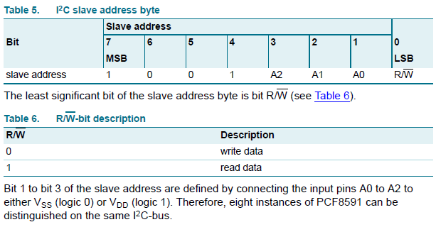
According to my knowledge address0x48is also ok. Please see documentation

Could you please suggest how can I get proper readings from this ADC via I2C?
-
@Wojciech-Glapiak Unfortunately the
i2cdetectcommand on Omega2(+) with the official FW is not working at all.My PCF8591 is powered up from 5v and I've check cables. they are ok.
According to my knowledge address0x48is also ok.You should powered it from 3.3V because the I2C bus of Omega2(+) is not 5V tolerant.
The I2C slave address of a PCF8591 demo board is usually 0x48. Do you have a demo board?
If you use a "bare" IC check that A0..A2 (pin 5,6,7) are tied to GND (pin 8).Suppose that the 0x48 slave address is correct and the default AIN0 (pin 1) is tied to GND.
The AD conversion is performed when you make a read request but the read will return the previous sample so it is always one sample behind.
i2cget -y 0 0x48
0x80
The first read after power on reset will return 0x80 - this is the power on reset status code.
Read again:
i2cget -y 0 0x48
0x00
This is the correct value that was sampled when you made the first read (the one that returned 0x80).Switch to read another input eg. AIN1 (pin 2) and it is also tied to GND:
i2cset -y 0 0x48 0x01
i2cget -y 0 0x48
0x_some_old_value
Read again:
i2cget -y 0 0x48
0x00 this is the correct valueAnd so on...
Good luck!
-
Thank you @György-Farkas for detailed answer.
I've tried this ADC (on demo board) on Arduino and also received nothing.
I think that this board is broken.
I bought ADS1115 and now I can smoothly read from photodiode
If somebody will need that in future guys from Control Everything Community made working python example for Omega2.
(or at least it's working in my case with FW: 0.2.0 b191)