GPIO connections may affect Omega operation
-
I know this is an old topic, but I think it might be resolved now.
I was also seeing this problem affecting GPIO13 (RX0). Since that GPIO belongs to the console serial port, it meant that if I ever rebooted with my console serial adapter connected, the Omega would not boot. At that point, the only way to get control of the Omega would be to disconnect the serial adapter and then power cycle it.
I am happy to report that my issue [at least] has been fixed with the firmware release 0.1.9. After installing that firmware, my device now reboots with the serial port adapter connected. So maybe these issues are also resolved for the other GPIOs mentioned above? Perhaps someone else can confirm.
-
The MT7688 does indeed have its startup mode configured by "strapping" of pullup/pulldown resistors on various GPIOs - the data sheet gives details.
An additional issue is that if you connect a USB-(logic level) serial adapter, the transmit line from the computer may actually "power" the chip and board just enough (through the data line) that you do not get a clean power-on-reset when you connect the actual power source.
-
I labelled the pins that configure startup mode for the MT7688 in red in the annotated pinout I made some time ago for the Omega2.
I made this pinout because I found it hard to determine which pins to use for what without having the complete per-pin functionality visible at a glance, and the red labels to remind me not to connect something which can pull up or down voltage during startup. Hope it's useful for others as well
")
-
Very helpful! Thanks.
-
Hi, I've never used an Omega and I've never written here, I write from Italy.
I'm developing a project considering an Omega2 module.
I plan to connect a Microchip MCP3008 ADC to the SPI bus
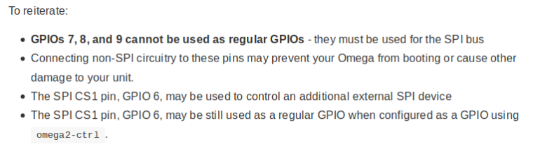
I read in the document "Using GPIOs" in the chapter "Important & Special pins" that at boot the pins GPIO6, GPIO7 and GPIO8, which is part of the SPI interface, should be left disconnected.
But how would it be possible to use an SPI device if it has to be unplugged at boot? Who will then link it into a forgotten box?
The pins mentioned should all be connected to the input pins of the MCP3008, could it still be a source of boot problems?
Any other warnings or suggestions on aspects that I missed?
Thanks.
Paolo.
-
@Paolo-carrer
Official Onion Omega2 Documentation
Using the Omega’s GPIOs
SPI Pins & Onboard Flash Storage
I think you will not have any hardware problems if you connect an MCP3008 to an Omega2 correctly. Try it!
-
@Paolo-carrer As @György-Farkas said, connecting a SPI peripheral to the SPI pins and using CS1 for selecting it should work fine.
The reasons for caution with the SPI pins are two-fold:
- the flash chip containing the firmware and user files is connected via these pins. If you use them in an improper way, it will likely affect access to the file system, crash the system or prevent it to boot, and if write operations are disturbed, also brick the Omega as a worst case. But as long as your external SPI device properly behaves and is off the bus when CS1 is not active, no problem here.
- In addition, the three SPI output pins (MOSI, SCK and CS1) also serve as CHIP_MODE inputs. This means right after reset or powerup, the logic level on these pins is sampled to configure how the chip starts up. To make these levels as needed at startup, the Omega2 has internal pullup and pulldown resistors on these pins. Now, if you connect something to these pins that has a lower impedance than those resistors, the CHIP_MODE will be wrong and the Omega will not start correctly. Again - a properly connected SPI chip should have high impedance MOSI, SCK and CS1 inputs, and will not disturb operation. But for example if you connected a LED to CS1 to see when your external device is selected, that would be a lower impedance and might change the CHIP_MODE at startup.
Note that there are more MODE pins that may not connect to anything of low impedance during startup for the same reason: GPIO1 (DRAM_TYPE), GPIO45/TX1 (JTAG_MODE) and GPIO12 (EXT_BGCK), and some more on the Omega2S.
That's why I marked them bright red on my extended pinout diagrams - it's too easy to forget about this when looking for a free GPIO otherwise
-
Very good, thanks.
-
Please, another small question.
I see in the Oled expansion schematic (https://github.com/OnionIoT/Onion-Hardware/blob/master/Schematics/Omega-OLED-Expansion.pdf)
that the SCL and SDA lines are not directly connected between Omega2 module and display, but there are two mosfets.
What is the need of two additional components?
There are another type of display that I can connect to Omega2 and that are already supported with software?
Or, If connect to Omega a LCD I2C display with UC1601S controller, is easy for my "informatic colleague" to write code to control it?
What type of controller is inside the Onion Oled expansion module?
Thanks to all.
-
@Paolo-carrer The OLED Expansion is hardware compatible with the original Omega and Omega2.
The Q1, Q2 FETs are 2.5V-to-3.3V I2C bus level shifters between the original Omega and the OLED display controller.
Q1, Q2 are 3.3V-to-3.3V I2C bus "level shifters" between Omega2 and the OLED display controller.Omega2 has I2C, SPI and serial interfaces so theoretically you could connect it to any display that has one of these interfaces.
Unfortunately only the OLED Expansion has full (out-of-the-box) Onion software support.
-
@György-Farkas said in GPIO connections may affect Omega operation:
@Paolo-carrer The OLED Expansion is hardware compatible with the original Omega and Omega2.
The Q1, Q2 FETs are 2.5V-to-3.3V I2C bus level shifters between the original Omega and the OLED display controller.
Q1, Q2 are 3.3V-to-3.3V I2C bus "level shifters" between Omega2 and the OLED display controller.Omega2 has I2C, SPI and serial interfaces so theoretically you could connect it to any display that has one of these interfaces.
Unfortunately only the OLED Expansion has full (out-of-the-box) Onion software support.Ok, thanks György
Just for clarity, if I use a 3,3V I2C slave device with Omega2, I not need the two translator fets in addition to pull-up res, right?
Do you know what display controller is inside the OLED Expansion? Or which Manufacturer/model is the OLED module?
-
@Paolo-carrer said in GPIO connections may affect Omega operation:
Just for clarity, if I use a 3,3V I2C slave device with Omega2, I not need the two translator fets in addition to pull-up res, right?
That's right.
I do not have any genuine Onion OLED Expansion.
Most probably every 128 x 64 Dot Matrix OLED modul has a Solomon Systech SSD1306 OLED Segment/Common Driver & Controller IC.
So please -> Google Search: SSD1306
-
Ok, many thanks.
I did DuckDuckGo Serach: SSD1306, it's right the same?
Best regards.