Starting up Omega2S on custom PCB
-
Hi All,
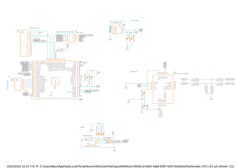
I am currently designing a multi PCB project with the Omega2S.
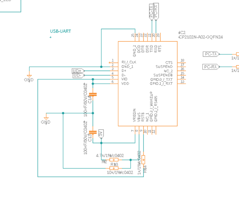
My issue is that I'm not able to get a Serial Connection to the Omega via the CP2102. The COM Port is detected and I can open a Session with Putty but it stays blank.
I also noticed that the Omega is consuming 800mA of current with occasional Spikes to 1.2A. That sounds like I fried it somehow.
Is there something fundamentally wrong with how I wired up the Omega or the CP2102?
-
At quick look, I am seeing the VIO is floating. It hould be connected to 3.3V internal regulator of CP2102 or just 3.3V power.
Here's a working circuit you can reference.
https://github.com/pcbcrew-org/omega2-4g-gateway/blob/develop/doc/schematics-v3.0a2.pdf
-
Interestingly in this Schematic they use the CP2102-GMT which seems to be the older model compared to the CP2102N Series. It does not have a VIO pin. However i rechecked the datasheet again and you are right that the VIO should be to 3.3V and RST then be bound to that 3.3V with a 1K resistor.
I also implemented a resistor divider to VBUS as recommended in the data sheet althought not scrictly needed. What I found odd in the schematic that you linked though is that the Omega is only connected to VDD_Flash but not to 3.3V. Any Idea why?
-
On the schematic, 3V3.1 and 3V32 pins are looking unconnected.
But it is because of a footprint error in the library. I imported the Omega2/2p symbol and footprint lib from SnapEDA and LCEDA was having a problem with net tag names starting with numbers.
If I connect the 3V3.1 and 3V3.2 pins to system power 3.3V, it is recognized as error and I could not route on the PCB editor.
So I let them be unconnected on Schematic and added net tags manually.
Just ignore those 3.3V wiring.
I had to fix the footprint lib, but I had no time to do it at the designing time.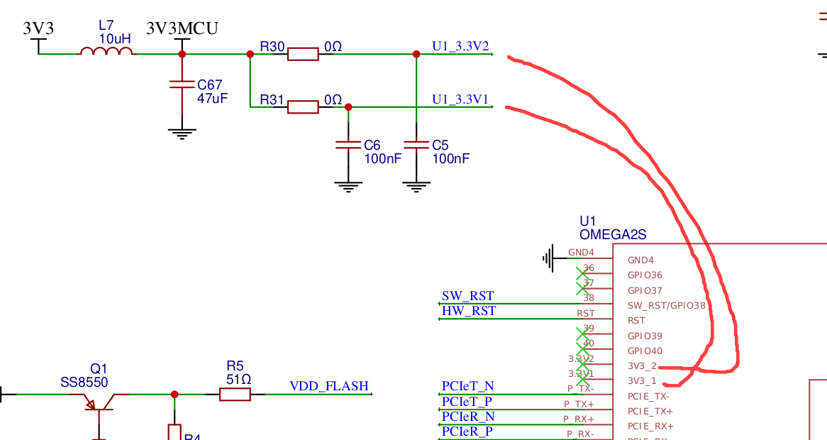
The schematics version v3.0a1 and v3.0a2 in the repository still has an error.
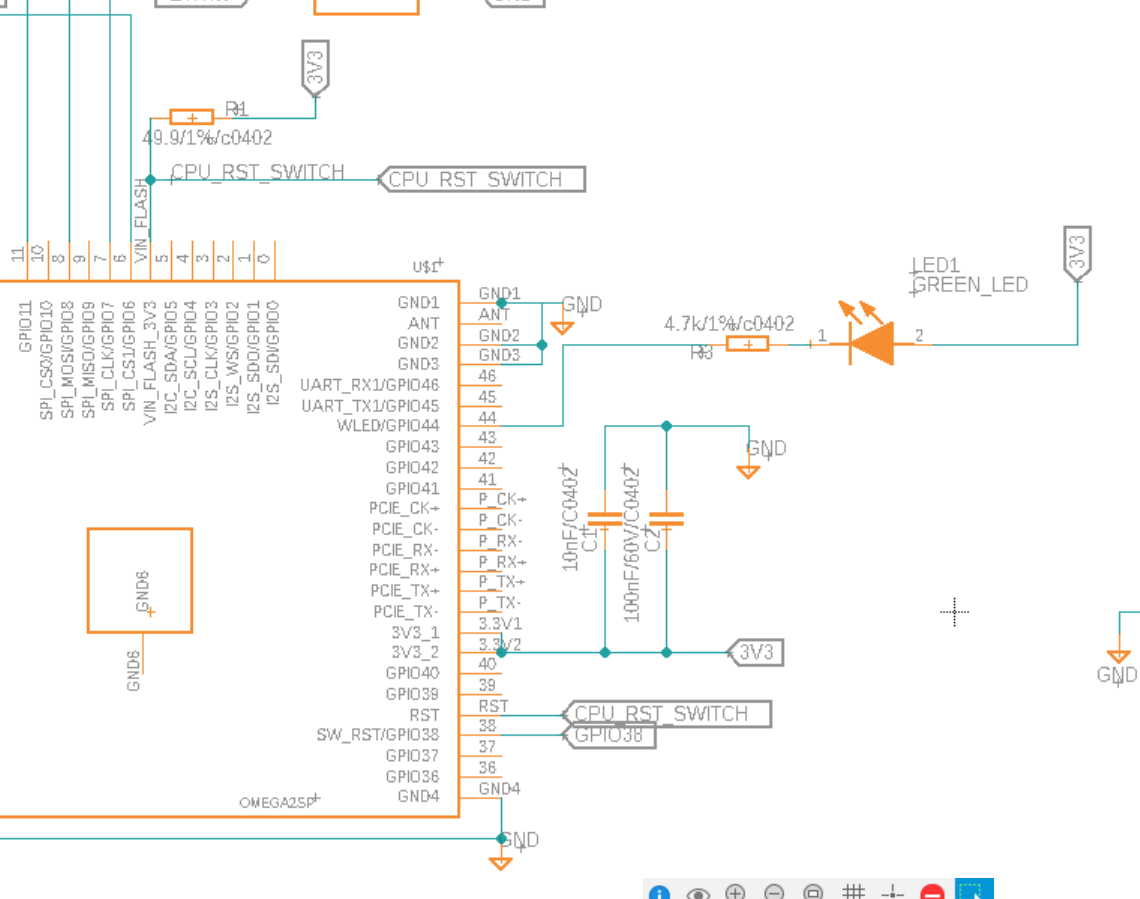
The emergency boot buttonSW_RSTshould be connected to 3V3.
Unlike most microcontrollers or SoMs, Omega2 has non-inverting logic.
-
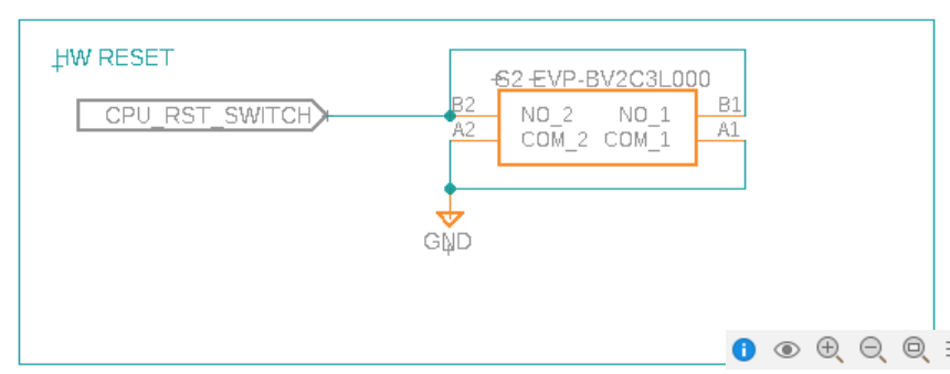
That makes Sense, so my Power Wiring should be correct. I see that in your schematic and in the datasheet the HW Reset and VDD_FLASH are connected via transistors. Any Benefit to that compared to just pulling them to GND via a Switch? CPU_RST_SWITCH simply bridges to GND.