SPI Pins for the Omega2
-
@Brice-Parent I don't need it, I'm using the SPI to communicate with a very simple MCP3008
-
I would like to report two issues with using SPI in Python on the Omega2. The first is that the transmit and receive buffers are only 16 bytes. There should be a mechanism in the driver that allows for DMA or interrupts to allow the use of a list longer than 16 bytes. The reason I say this is that the best time between SPI bursts is about 150uS. In other words, the following code;
spi.write([[0xAA, 0x55, 0xAA])
spi.write([[0xAA, 0x55, 0xAA])will result in about 150uS between SPI transmissions. If the SPI driver would recognize that the list passed in is longer than the built-in queues and then use an interrupt or DMA to keep the queue full until the list was exhausted then a list with several hundred bytes could be sent as one continuous transmission. This would facilitate using the SPI device to drive strings of NeoPixels. As it stands now, only a string of one NeoPixel can be driven by the SPI device. This would also help in using the SPI to communicate with an SPI based tft LCD or any device that requires more than 16 bytes in a continuous burst.
The second issue is that the first byte transmitted always sets the most significant bit to zero (when MSB first). So sending 0xAA results in 0x2A being sent. Not good. This only happens to the first byte of each burst. The only thing I changed from default was the bitrate.
Finally, a complaint that seems to be echoed everywhere in the world of the Omega2. That is the lack of documentation. What is available has mistakes, references the Omega or leaves a lot of information out.
-
@James-Behrens I've open a ticket 12 days ago about that, without the 150uS delay that I didn't know about (I don't have a scope), but so far no answer from the team. I'll link it to your post for more info.
Also, if you find a workaround to be able to use more than 16 bytes without having to wait for a software update, like a software SPI or another library, please tell me about it.
-
Have a look at this defect:
https://dev.openwrt.org/ticket/20521
That's surely the root cause of this issue in Omega2; it's in the upstream source and may represent a hardware limitation of the MT7688/7621 SoC.
-
... and the more I look at this, I think this may not be a bug. The MT7688 hardware can handle only so many bytes per hardware transfer, but it looks like the Linux SPI permits a transfer to be broken into an array of transfers that are processed with a single Chip Select - chaining them together. So it may be some additional work is required in the C and Python libs.
-
So - about the leading bit of 'address' (which is not a pure SPI construct - there's no requirement for an address to be the first byte of a transfer, or even for transfers to be in bytes). On a hunch, I tried values of address with the top two bits being '10' (example, 0xaa, 0xb2, 0x88, etc.) and values of address with the top two bits being '11' (ex. 0xc0, 0xff, etc.) and found that anything with '10' in the top two bits loses the MSB (transfers it as '0') and anything with '11' in the top two bits transfers it correctly. My test hardware SPI slave is an Atmel ATmega1284P , with the clock phase/polarity set to 0 (which matches the default settings in the Linux driver) (any other settings in the AVR SPI slave corrupt the data). I tried reducing the clock rate and adding a delay but never helped.
So I'm guessing there's a timing/phase issue there; I'll have to get the oscilloscope out and have a look.
-
@James-Behrens as you probably have seen in my messages; the Omega Python library needs to break up the SPI transfer into 16-byte chunks and chain them together in the SPI_IOC_MESSAGE() call - I think that'll solve the transfer limitation. The loss of the MSB in the first byte (aka address) happens when the top two bits are '10' and not when they're '11' and that's apparently something in the MT7688 SPI driver and/or timing of the SPI slave.
-
So here's a capture of CLK and MOSI from "spi-tool write 0xaa 0x11":
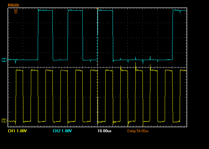
Upper trace is MOSI, lower trace is CLK, aligned to the vertical grid (10uS). You see the CLK leading-edge transitions are in the middle of the data - it all looks right except the first '1' bit is missing (far left, the first clock transition occurs while MOSI is 0).
This is "spi-tool write 0xca 0x11":
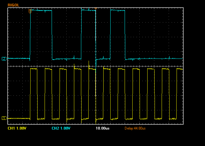
So here, MOSI starts with an abbreviated '1' bit, only about 1/2 as long as it should be, though the rest of the data timing is correct.
There are two problems:
- list itemWhen the first two bits are '10', the leading '1' is completely not sent by the SPI peripheral.
- list itemWhen the first two bits are '11', the leading '1' is about half as long as it should be.
This makes me think something is amiss with the SPI peripheral - perhaps some timing in the MT7621 SPI driver?
-
Oh - a known bug in the MT7688:
-
I noticed this bug myself, too, though I wasn't entirely sure, if it was something I did wrong with my custom images. Then I got distracted with other things in life and forgot to investigate this further. Anyways, if someone wishes to test, I compiled custom images for Omega2 and Omega2+, that include a patch for the SPI-stuff -- both images and a good bunch of various kernel-modules can be found inside https://dl.dropboxusercontent.com/u/11811685/omega2-stuff/omega2-spi-test.tar.bz2
I don't have many SPI-devices to test with, nor do I have a logic-analyzer to look at the output with, and besides, I'm quite occupied with other stuff at the moment, so I can't test how/if SPI works any better now. If someone here does get around to testing the images, I would appreciate hearing about the results. My images work similar to the official ones, ie. it sets up an AP on first boot and such, and you can use a web-interface to configure it. Don't forget to flash with
sysupgrade -n /tmp/image.bin-- has to be in /tmp and you should use the "-n" flag.EDIT: I forgot to mention that I included various SPI-related tools in the image, so there's no need to install them from the repos.
-
@WereCatf Which patch did you use? I'm integrating and unit-testing the patch I found in the Mediatek Labs forum; same one?
-
@Dana-Myers114 Aye, that one, yes.
-
@WereCatf @WereCatf I'm fixin' to test that patch myself; any hints on generating the LEDE build? I'm rather hoping I can
a) Add the onion feed to feeds.conf.default with this line:
src-git onion https://github.com/OnionIoT/OpenWRT-Packages.git;omega2b) start with .config :
CONFIG_TARGET_ramips=y
CONFIG_TARGET_ramips_mt7688=y
CONFIG_TARGET_ramips_mt7688_DEVICE_omega2=yfollowed by make defconfig
After that, make menuconfig and select spi-tool + Python lib, then sysupgrade my test target. Is there any reason '-n' is required in the sysupgrade? I have a serial console anyway but I figure a regular sysupgrade ought to work OK if I make sure to include the Mediatek SoftAP driver from the onion feed.
Once I establish the baseline build works, I'll drop in the patched spi-mt7621.c source and
spin it.Any hints?
-
@Dana-Myers114 said in SPI Pins for the Omega2:
Is there any reason '-n' is required in the sysupgrade?
I just say it, because my builds don't include the proprietary WiFi-driver and so not all the config-files apply. It's easier to just reset all settings to default, so they don't cause any issues.
-
@WereCatf OK - I may actually get test bits tonight and report back. SPI slave target is an Atmel AVR (ATmega1284P at the moment, but I'll be shifting to an ATmega328PB as soon as SPI functionality is verified, though that really makes no difference).
Assuming the patch works - I suppose it's begging to be a pull request upstream, really rather not maintain my own fork of the base OS.
Thanks again.
-
@WereCatf I generated my own build (LEDE + Onion feed), incorporated berniwa's patch to spi-mt7621, and am pleased to report it's working for me so far (testing with both spi-test and pyOnionSpi). My SPI slave target is an Atmel ATmega1284P and I'm validating the behavior in the ATmega using a JTAG debugger.
I also flashed an O2+ with your provided image, and verified it with spi-tool. Of course, both of our patches include this warning:
             if (t->tx_buf && t->rx_buf) {
                    printk(KERN_ERR
                        "The MT7621-SPI does not support full"
                        " bidirectional SPI, only doing TX!");
            }
which generates arguably gratuitous chatter and probably ought to be removed (I'm removing it from my version of the patch).
I also validated larger than 16-byte transfers work correctly (I tested writes, since my slave device is currently very simple and doesn't talk back yet).
Pending a bit more testing, this patch seems like it ought to back upstream - would you consider doing the PR?
Thanks for the help!
-
@Dana-Myers114 Sounds promising! I was just planning to test it out myself today with a fancy little project and, if it works, I'll report back here and then possibly discuss the patch with upstream.
-
I really, really want a logic-analyzer for this stuff, god dammit.
-
@WereCatf said in SPI Pins for the Omega2:
I really, really want a logic-analyzer for this stuff
Basic cy7c68013a board and sigrok is a cheap, effective solution for moderate speeds
-
So, I just obtained a logic-analyzer a couple of days ago and I tried to get fbtft running on the Omega2, but it's a no-go so far. While the kernel-module itself technically works and I am seeing the expected data on the SPI-bus, the display doesn't work.
I took a capture from two other SBCs and the only meaningful difference I can see is that the Omega2 starts the SPI-bus clock and data-transfer immediately as it pulls the CS-pin low, whereas the other two SBCs pull CS-pin low, then wait 12 microseconds before starting the clock and data-transfer -- I have no idea, if this is a standard-procedure or if it is even the cause, but that's the only thing I can see, that jumps out at me.