Omega2+ Reboot Fix [Official Solution]
-
Lately there has been a lot of discussions about the Omega2+ not being able to boot after unexpected reset. We did some digging and found a solution.
The Problem
In short here is what we have identified as the root of the issue.
- By default both the Omega2+ CPU and Flash memory boots from a 3 Byte address mode
- During boot loader the CPU upgrades both Flash memory and itself to a 4 Byte address mode in order to access higher memory addresses
- During an unexpected reset (brownout) the CPU resets but the memory remains in the 4 Byte address mode.
- The mismatch in the address mode prevent the CPU from booting normally.
- A power cycle at this point will reset the Flash memory back to 3 Byte mode and the system will boot normally
Here is a table summarizing different boot conditions:
Boot State GPIO 6 (SPI CS1) State CPU address mode Flash address mode Boot Result Cold boot Default (pull down) 3 Byte 3 Byte Success Hot boot Default (pull down) 3 Byte 4 Byte Fail Cold boot Pull Up 4 Byte 3 Byte Fail Hot boot Pull Up 4 Byte 4 Byte Success The Fix
According to the above table we need to build a solution to have GPIO 6 pulled sown during cold boot and pulled up in at hot boot in order for the system to boot successfully in both conditions. The following circuit does just that.
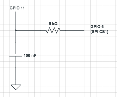
- During a cold boot GPIO 11 starts as LOW
- GPIO 6 is reads LOW
- During boot the boot loader sets GPIO 11 High (Originally used to provide power to the user pushbutton on Omega2 docks)
- This will charge up the capacitor to 3.3V
- During an unexpected reset or hot boot, the capacitor will temporarily pull GPIO 6 High setting the CPU to boot from a 4 Byte address mode
Please let us know if this setup helps with your situation. We would also like to hear if anyone have came up with a software only solutions. So far we have not yet figured out a way to make the flash memory to cold boot from a 4 Byte address mode.
Here is the Flash memory data sheet for those who are interested in dig deeper MX25L25635E.pdf
-
The most perfect solution is to use the 4Byte-Address mode for 32MB FLASH, and pull up to 3.3V before CS1 starts.
-
I'd like to test this. I'm motivated as I have field deployed units that will fail, making me very unpopular with my client.
I probably have all of the test equipment required to create an automated test that could execute tens of thousands of test permutations with no human in the loop.
Do any of the Onioneers have any interest in collaborating with me in creating a test plan and test procedure, perhaps writing a few lines of code, etc.? My up front view is to do it in public view on this forum, unless our friends at Onion suggest otherwise. If the latter, we'd collaborate in some other fashion.
Anyone interested?
--Bill
-
@William Scott
We are happy to collaborate in coming up with an automated tests procedure. Doing it publicly here on the community is definitely the way to go. This way more people can contribute of rip the benefit of the test result.
Can you share what test setup you have in mind and specifically what input do you need from Onion side?
-
@Zheng-Han I have some loose ideas that go back to doing qualification testing on avionics systems. In general. designing a circuit including some automatic test equipment that will cause brownouts. Aircraft are notoriously dirty with respect to power. Avionics systems must be able to survive in a nasty electrical environment.
In avionics (e.g. DO-160 or MIL-STD-810) brownouts are defined as percent reduction from defined power supply over a time window. For example, 40% below 5vdc (or 3.3vdc) for 150 milliseconds. I'd like to design a test that would, in repeatable fashion, allow us to test system survivability over a broad spectrum of voltage levels and outage periods.
I invite the community to participate in defining what those test parameters would be. That would probably be a good next step.
--Bill
-
I've created a new thread for the validation of the fix as I believe it will have a life of its own. This will allow the community to keep this thread brief and to the point. The new thread is at --> http://community.onion.io/topic/3062/analysis-and-test-of-omega2-reboot-fix-official-solution
--Bill
-
@Zheng-Han I tried your "Official Solution" to fix the 3 Byte / 4 Byte flash problem of Omega2+ with FW v0.2.0 b192.
Good News
-
After more than two years you are finally trying to do something about this problem.
-
What was working up until now still seems to be working:
- Power On - cold boot - Success
- short or long press the FW_RST button - warm boot - Success
reboot,firstboot- warm boot - Success
Bad News
- During this two years there was no official announcement (confession
")
Dear Omega2+ Customers,
We are very sorry the Winbond 25Q256FV / Macronix MX25L25635E 32MB flash chip was an especially bad choice.
Each Omega2+ ab ovo has a HW bug (a factory fault) because of this.
Our plan is the following...- What wasn't working up until now still seems faulty
- press the HW_RST button - cold boot - Fail
- kernel panic - warm boot - Fail
for example with the MediaTek WiFi driver up to FW v0.1.10 b160
[ 28.858759] Kernel panic - not syncing: stack-protector: Kernel stack is corrupted in: 8701d944
[ 28.858759]
[ 28.872523] Rebooting in 3 seconds..
about brownout
@Zheng-Han wrote
During an unexpected reset (brownout) the CPU resets but ...
Why do you think so?
Brownout is a power supply related unwanted event - it is not a reset.
If I know well neither the MT7688A SoC has got internal brownout detector / circuit
nor the Omega2+ board has got any device / circuit to reset the CPU during or after a brownout.
Correct me if I'm wrong please.You should specify what does brownout and unexpected reset mean for you.
Although your reasoning, some of your conclusions are not entirely clear for me I'll try to test your whole theory.
about GPIO 11
@Zheng-Han wrote
During boot the boot loader sets GPIO 11 High (Originally used to provide power to the user pushbutton on Omega2 docks)
There are no such Omega2 Docks. Please show us a planned schematic about that user pushbutton.
What do you think about my thought:
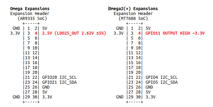
There are I2C level shifters on the OLED Expansion and the PWM / Servo Expansion:
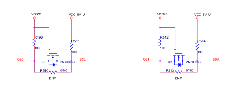
VDD25 ie. 2.5V (or 3.3V of the GPIO11 OUTPUT HIGH) is the power supply of the lower voltage section - the circuit does not work without it.
-
-
@Zheng-Han Sorry, I think your circuit is not necessary.
The warm boot is not depend on the state of GPIO 6 (SPI CS1) - the default config is perfect.@Zheng-Han wrote
During an unexpected reset or hot boot, the capacitor will temporarily pull GPIO 6 High setting the CPU to boot from a 4 Byte address mode
GPIO 6 (SPI CS1) default config / default state - internal pulldown
   Ω-ware: 0.2.0 b194
 -----------------------------------------------------
root@Omega-5BE1:/# reboot
root@Omega-5BE1:/# [ 8102.452960] br-wlan: port 1(ra0) entered disabled state
[ 8102.473391] device ra0 left promiscuous mode
[ 8102.477842] br-wlan: port 1(ra0) entered disabled state
[ 8106.781266] Removing MTD device #6 (rootfs_data) with use count 1
[ 8106.810481] reboot: Restarting system


   ____       _             ____
  / __ \___  (_)__  ___    / __ \__ _  ___ ___ ____ _
 / /_/ / _ \/ / _ \/ _ \  / /_/ /  ' \/ -_) _ `/ _ `/
 \____/_//_/_/\___/_//_/  \____/_/_/_/\__/\_, /\_,_/
 W H A T  W I L L  Y O U  I N V E N T ? /___/"

Board: Onion Omega2 APSoC DRAM:  128 MB
relocate_code Pointer at: 87f60000
******************************
Software System Reset Occurred
******************************
flash manufacture id: c2, device id 20 19
find flash: MX25L25635E
============================================
Onion Omega2 UBoot Version: 4.3.0.3
--------------------------------------------
ASIC 7628_MP (Port5<->None)
DRAM component: 1024 Mbits DDR, width 16
DRAM bus: 16 bit
Total memory: 128 MBytes
Flash component: SPI Flash
Date:Oct 18 2016  Time:17:29:05
============================================
icache: sets:512, ways:4, linesz:32 ,total:65536
dcache: sets:256, ways:4, linesz:32 ,total:32768
CPU freq = 575 MHZ
Estimated memory size = 128 Mbytes
Resetting MT7628 PHY.
Initializing MT7688 GPIO system.


**************************************
* Hold Reset button for more options *
**************************************


Boot Linux from Flash NO RESET PRESSED.
## Booting image at bc050000 ...
   Image Name:   MIPS LEDE Linux-4.4.74
   Image Type:   MIPS Linux Kernel Image (lzma compressed)
   Data Size:    1341905 Bytes =  1.3 MB
   Load Address: 80000000
   Entry Point:  80000000
   Verifying Checksum ... OK
   Uncompressing Kernel Image ... OK
No initrd
## Transferring control to Linux (at address 80000000) ...
## Giving linux memsize in MB, 128

Starting kernel ...

[    0.000000] Linux version 4.4.74 (root@3fbe4dcb626f) (gcc version 5.4.0 (LEDE GCC 5.4.0 r3484-d8f14ba) ) #0 Tue Jul 31 16:32:08 2018
GPIO 6 (SPI CS1) Reboot Fix the [Official Solution]
   Ω-ware: 0.2.0 b194
 -----------------------------------------------------
root@Omega-5BE1:/# reboot
root@Omega-5BE1:/# [   65.628024] br-wlan: port 1(ra0) entered disabled state
[   65.651352] device ra0 left promiscuous mode
[   65.655871] br-wlan: port 1(ra0) entered disabled state
[   69.967037] Removing MTD device #6 (rootfs_data) with use count 1
[   69.996395] reboot: Restarting system


   ____       _             ____
  / __ \___  (_)__  ___    / __ \__ _  ___ ___ ____ _
 / /_/ / _ \/ / _ \/ _ \  / /_/ /  ' \/ -_) _ `/ _ `/
 \____/_//_/_/\___/_//_/  \____/_/_/_/\__/\_, /\_,_/
 W H A T  W I L L  Y O U  I N V E N T ? /___/"

Board: Onion Omega2 APSoC DRAM:  128 MB
relocate_code Pointer at: 87f60000
******************************
Software System Reset Occurred
******************************
flash manufacture id: c2, device id 20 19
find flash: MX25L25635E
============================================
Onion Omega2 UBoot Version: 4.3.0.3
--------------------------------------------
ASIC 7628_MP (Port5<->None)
DRAM component: 1024 Mbits DDR, width 16
DRAM bus: 16 bit
Total memory: 128 MBytes
Flash component: SPI Flash
Date:Oct 18 2016  Time:17:29:05
============================================
icache: sets:512, ways:4, linesz:32 ,total:65536
dcache: sets:256, ways:4, linesz:32 ,total:32768
CPU freq = 575 MHZ
Estimated memory size = 128 Mbytes
Resetting MT7628 PHY.
Initializing MT7688 GPIO system.


**************************************
* Hold Reset button for more options *
**************************************


Boot Linux from Flash NO RESET PRESSED.
## Booting image at bc050000 ...
   Image Name:   MIPS LEDE Linux-4.4.74
   Image Type:   MIPS Linux Kernel Image (lzma compressed)
   Data Size:    1341905 Bytes =  1.3 MB
   Load Address: 80000000
   Entry Point:  80000000
   Verifying Checksum ... OK
   Uncompressing Kernel Image ... OK
No initrd
## Transferring control to Linux (at address 80000000) ...
## Giving linux memsize in MB, 128

Starting kernel ...

[    0.000000] Linux version 4.4.74 (root@3fbe4dcb626f) (gcc version 5.4.0 (LEDE GCC 5.4.0 r3484-d8f14ba) ) #0 Tue Jul 31 16:32:08 2018
GPIO 6 (SPI CS1) pulldown 1 kOhm to GND
   Ω-ware: 0.2.0 b194
 -----------------------------------------------------
root@Omega-5BE1:/# reboot
root@Omega-5BE1:/# [  623.732112] br-wlan: port 1(ra0) entered disabled state
[  623.745535] device ra0 left promiscuous mode
[  623.750045] br-wlan: port 1(ra0) entered disabled state
[  628.070148] Removing MTD device #6 (rootfs_data) with use count 1
[  628.099556] reboot: Restarting system


   ____       _             ____
  / __ \___  (_)__  ___    / __ \__ _  ___ ___ ____ _
 / /_/ / _ \/ / _ \/ _ \  / /_/ /  ' \/ -_) _ `/ _ `/
 \____/_//_/_/\___/_//_/  \____/_/_/_/\__/\_, /\_,_/
 W H A T  W I L L  Y O U  I N V E N T ? /___/"

Board: Onion Omega2 APSoC DRAM:  128 MB
relocate_code Pointer at: 87f60000
******************************
Software System Reset Occurred
******************************
flash manufacture id: c2, device id 20 19
find flash: MX25L25635E
============================================
Onion Omega2 UBoot Version: 4.3.0.3
--------------------------------------------
ASIC 7628_MP (Port5<->None)
DRAM component: 1024 Mbits DDR, width 16
DRAM bus: 16 bit
Total memory: 128 MBytes
Flash component: SPI Flash
Date:Oct 18 2016  Time:17:29:05
============================================
icache: sets:512, ways:4, linesz:32 ,total:65536
dcache: sets:256, ways:4, linesz:32 ,total:32768
CPU freq = 575 MHZ
Estimated memory size = 128 Mbytes
Resetting MT7628 PHY.
Initializing MT7688 GPIO system.


**************************************
* Hold Reset button for more options *
**************************************


Boot Linux from Flash NO RESET PRESSED.
## Booting image at bc050000 ...
   Image Name:   MIPS LEDE Linux-4.4.74
   Image Type:   MIPS Linux Kernel Image (lzma compressed)
   Data Size:    1341905 Bytes =  1.3 MB
   Load Address: 80000000
   Entry Point:  80000000
   Verifying Checksum ... OK
   Uncompressing Kernel Image ... OK
No initrd
## Transferring control to Linux (at address 80000000) ...
## Giving linux memsize in MB, 128

Starting kernel ...

[    0.000000] Linux version 4.4.74 (root@3fbe4dcb626f) (gcc version 5.4.0 (LEDE GCC 5.4.0 r3484-d8f14ba) ) #0 Tue Jul 31 16:32:08 2018
GPIO 6 (SPI CS1) pullup 1 kOhm to 3.3V only for this test of course.
   Ω-ware: 0.2.0 b194
 -----------------------------------------------------
root@Omega-5BE1:/# reboot
root@Omega-5BE1:/# [  966.150735] br-wlan: port 1(ra0) entered disabled state
[  966.168874] device ra0 left promiscuous mode
[  966.173328] br-wlan: port 1(ra0) entered disabled state
[  970.490053] Removing MTD device #6 (rootfs_data) with use count 1
[  970.519287] reboot: Restarting system


   ____       _             ____
  / __ \___  (_)__  ___    / __ \__ _  ___ ___ ____ _
 / /_/ / _ \/ / _ \/ _ \  / /_/ /  ' \/ -_) _ `/ _ `/
 \____/_//_/_/\___/_//_/  \____/_/_/_/\__/\_, /\_,_/
 W H A T  W I L L  Y O U  I N V E N T ? /___/"

Board: Onion Omega2 APSoC DRAM:  128 MB
relocate_code Pointer at: 87f60000
******************************
Software System Reset Occurred
******************************
flash manufacture id: c2, device id 20 19
find flash: MX25L25635E
============================================
Onion Omega2 UBoot Version: 4.3.0.3
--------------------------------------------
ASIC 7628_MP (Port5<->None)
DRAM component: 1024 Mbits DDR, width 16
DRAM bus: 16 bit
Total memory: 128 MBytes
Flash component: SPI Flash
Date:Oct 18 2016  Time:17:29:05
============================================
icache: sets:512, ways:4, linesz:32 ,total:65536
dcache: sets:256, ways:4, linesz:32 ,total:32768
CPU freq = 575 MHZ
Estimated memory size = 128 Mbytes
Resetting MT7628 PHY.
Initializing MT7688 GPIO system.


**************************************
* Hold Reset button for more options *
**************************************


Boot Linux from Flash NO RESET PRESSED.
## Booting image at bc050000 ...
   Image Name:   MIPS LEDE Linux-4.4.74
   Image Type:   MIPS Linux Kernel Image (lzma compressed)
   Data Size:    1341905 Bytes =  1.3 MB
   Load Address: 80000000
   Entry Point:  80000000
   Verifying Checksum ... OK
   Uncompressing Kernel Image ... OK
No initrd
## Transferring control to Linux (at address 80000000) ...
## Giving linux memsize in MB, 128

Starting kernel ...

[    0.000000] Linux version 4.4.74 (root@3fbe4dcb626f) (gcc version 5.4.0 (LEDE GCC 5.4.0 r3484-d8f14ba) ) #0 Tue Jul 31 16:32:08 2018
It's quite hard to reproduce your "large capacitor" test if you don't tell us any details
More tests - probably more to come...
-
My thoughts are as follows.
- Build a circuit in which the O2+ receives it's supply voltage through a FET.
- Downstream of the FET would be a voltage regulator (3.3 or 5v, whichever is being tested) to prevent an over voltage condition that may damage a part (I'ved killed approx five Expansion Docks by powering them via a laptop and uUSB cable!!!).
- Upstream of the FET would be the power supply.
- The gate of the FET would be attached to a function generator.
- The function generator would be set to provide a "pulse" of the test duration, allowing for some automation to get to many, many brown out duration variants.
- The non-pulsed input would allow for full input voltage. The negative pulse would be of sufficient magnitude to allow for various depths of the brown out. You could think of the ambient function generator output as proxy for the full input power supply and a pulse in the direction of 0 volts to be a proxy for the reduced input.
- This may lend itself to automation such that we could do "four corners" test with hundreds or even thousands of permutations.
- Of course a rebooting O2+ would be unavailable for another test run for over a minute, so let's not get too greedy on the "thousands" of test permutations.
- I may have the test equipment to do this (I think I do).
Any comments or other ideas?
--Bill
-
@William-Scott My bad - I wanted to post this in the new thread for validation. I'll copy/paste, so if you look at the other thread, this will look eerily similar.
--Bill
-
I flashed a snapshot version of OpenWRT and I noticed that the reboot command doesn't work.
Onion omega2+ stays in a like infinity loop and it doesn't respond until I perform power cycle.
I also noticed that this bug has been solved in latest releases of onion firmware (Ω-ware).Is there anything I can do to solve this bug on OpenWRT branch?
What is the official software solution for that?
-
A software fix for the unexpected reboot case is possible, at least for recently manufactured Omega2+ boards.
The driver identifies the flash chip as a MX25L25635E, and Onion have provided the datasheet for the same. But this chip was was superseded by the MX25L25635F in 2012, and by the MX25L25645G in 2020. Both revisions included a process change, and Macronix deliberately retained the old JEDEC ID so that the new part could be a drop-in replacement, so I would find it surprising if E revision were still broadly available to manufacturers today. The F and G revisions support 4-byte opcodes, so the host can access memory beyond 16M while keeping the chip always in 3-byte address mode.
I modified OpenWrt v19.07.7, which normally hangs on reboot, to select the F instead of the E chip, and installed it on an Omega2+ purchased in 2021. Reboots now work correctly, and yes, I confirmed that the upper part of the flash memory is accessible as well.
So the first question is, do all the boards out there use the F chip or did earlier manufacturing runs get the E? Onion's fix to reset the address mode on shutdown relies on commands that are only documented in the F datasheet and not the E. So chances are good that it's been the F all along... but if somebody with older hardware could test, that would give more confidence than drawing conclusions from the absence of a command in the datasheet.
The second question is can we upstream a fix into OpenWrt, which definitely needs to support the E chip on non-onion devices? Recall that we can't use the JEDEC ID to differentiate because the IDs are the same. The mainline kernel already handles this by looking at the Basic Flash Parameters Table. Unfortunately the driver in OpenWrt bales out before loading the BFPT because the SFDP signature from the chip reads as 0xFFFFFFFF instead of the magic value it expects. The latter problem also occurs on an Omega2S+ which has the completely different W25Q256 flash chip. So I think reading the flash parameters is just broken in OpenWrt, but there have been so many changes to the SPI NOR code in mainline since the 4.14 branch that I wasn't able to find a promising patch to backport.
It's worth noting that some OpenWrt users fix this by naming a specific flash chip in their device tree config, rather than relying on the ambiguous JEDEC ID lookup. This isn't a good solution for Onion, however, because a single .bin file today is usable by the Omega2+ and Omega2S+, and hardcoding a name would require two separate builds.
I'm going to fix my application by installing my patch into the target/linux/ramips/patches-4.14 directory of OpenWrt before builds. You may want to do the same, but do your own testing in case any boards with an E chip are out there which would break. Hopefully when OpenWrt moves to a 5.x kernel we can have a more general fix.
-
This post is deleted!