SPI SSD1306 Display boot problem
-
Re: Using Touch Screen with Omega2
Hi everyone. Currently I'm working in a project that uses the SPI version of the SSD1306 Display, I'm connecting it to the native SPI bus of the Omega2+ and as @luz said in the linked post, I've encountered that the board won't boot when the display is connected, however, if I disconnect it during boot and then connect it, it works just fine. I've isolated the issue to the MOSI pin, this suprised me since the Omega2+ datasheet doesn't say that this pin is important for the boot sequence.
With that said, I would like to know if anyone has encountered this problem with this or other SPI device and knows why it happens or, even better, how to solve it, because disconnecting the device during the boot sequence is not an option.
Thank you!
-
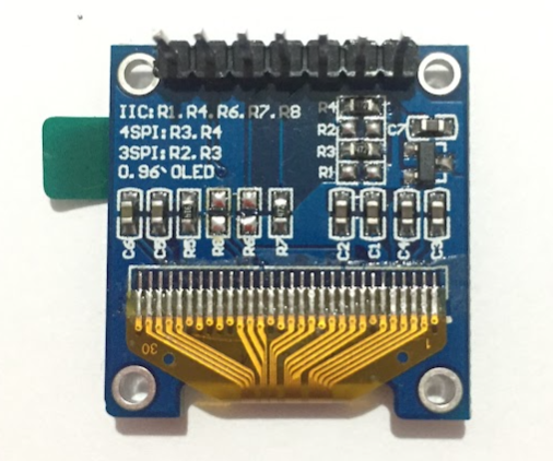
I was able to solve it and since I haven't seen this online anywhere, I think it might be helpful to explain it here. Turns out, that the model of SSD1306 I'm using comes with three operation modes: I2C, 3-wire SPI and 4-wire SPI. By default, 4-wire SPI is used, however, it comes with what I think is a pull-up resistor marked as R6 for the I2C mode, which also serves as the MOSI pin for the 4-wire SPI mode. I desoldered R6 as shown in the attached image and now the Omega2+ boots with no problem and I was able to use the display using Blinka and the python driver from Adafruit.
-
Thank you very much, this is interesting information!
MOSIis indeed one of the bootstapping pins, calledCHIP_MODE_2.
However, the MT7688 only has 4 modes, which are defined byCHIP_MODE_1andCHIP_MODE_0alone - see page 31 of the MT7688 Datasheet.The datasheet does specify that
CHIP_MODE_2should be 0, but it does not say whatCHIP_MODE_2==1 would mean.Unlike the other bootstrap pins, which are documented to have pullups or pulldowns inside the Omega2(S), I never found an indication that
CHIP_MODE_2does have a pulldown. The Omega2S datasheet just says thatMOSIcan't be used as a GPIO (obviously, as it is used by the SPI flash), but nothing about pullup/downs.So my working assumption till now was that
CHIP_MODE_2is not actually sampled at SoC boot - which turns out to be wrong!Apparently, it is important that
CHIP_MODE_2/MOSIis 0 at boot, so I guess there must be a weak pulldown somewhere, be it in the Omega2(S) or in the SoC itself.And in consequence, as you found out, that pin must not have external pullups...
So I just updated my annotated Omega2 + Omega2S pinouts accordingly.
@Lazar-Demin: maybe it would make sense to mark the
MOSIpin red in the datasheet too? And btw., the MT7688 datasheet links you have in the onion docs no longer work - I found this one as a replacement.
-
good call!
@luz said in SPI SSD1306 Display boot problem:
maybe it would make sense to mark the MOSI pin red in the datasheet too?
Released v1.9 of Omega2S datasheet and v1.2 of Omega2 datasheet that includes
SPI MOSIas a pin that's important for boot and must be floating.@luz said in SPI SSD1306 Display boot problem:
And btw., the MT7688 datasheet links you have in the onion docs no longer work
Thanks for the heads up! Updated the link to a copy that Onion hosts, so this should work indefinitely.