@Brice-Parent I've got a patch that I apply in my own build; I suppose I could do a PR for it into the Onion repo, though I think it really should go upstream into LEDE/OpenWRT. Before doing a PR for that, I need to confirm that this issue is present in all MT7621-type SPI peripherals (not just in the MT7688 used in the Omega2) because it would patch all of them. Given that actual full-duplex operation is not possible with the patch, it is potentially a regression if there's a flavor of MT7621 SPI that actually does work (though I suspect that's not the case)
Posts made by Dana Myers114
-
RE: SPI Pins for the Omega2posted in Omega Talk
-
RE: gps receiver not lockingposted in Omega Talk
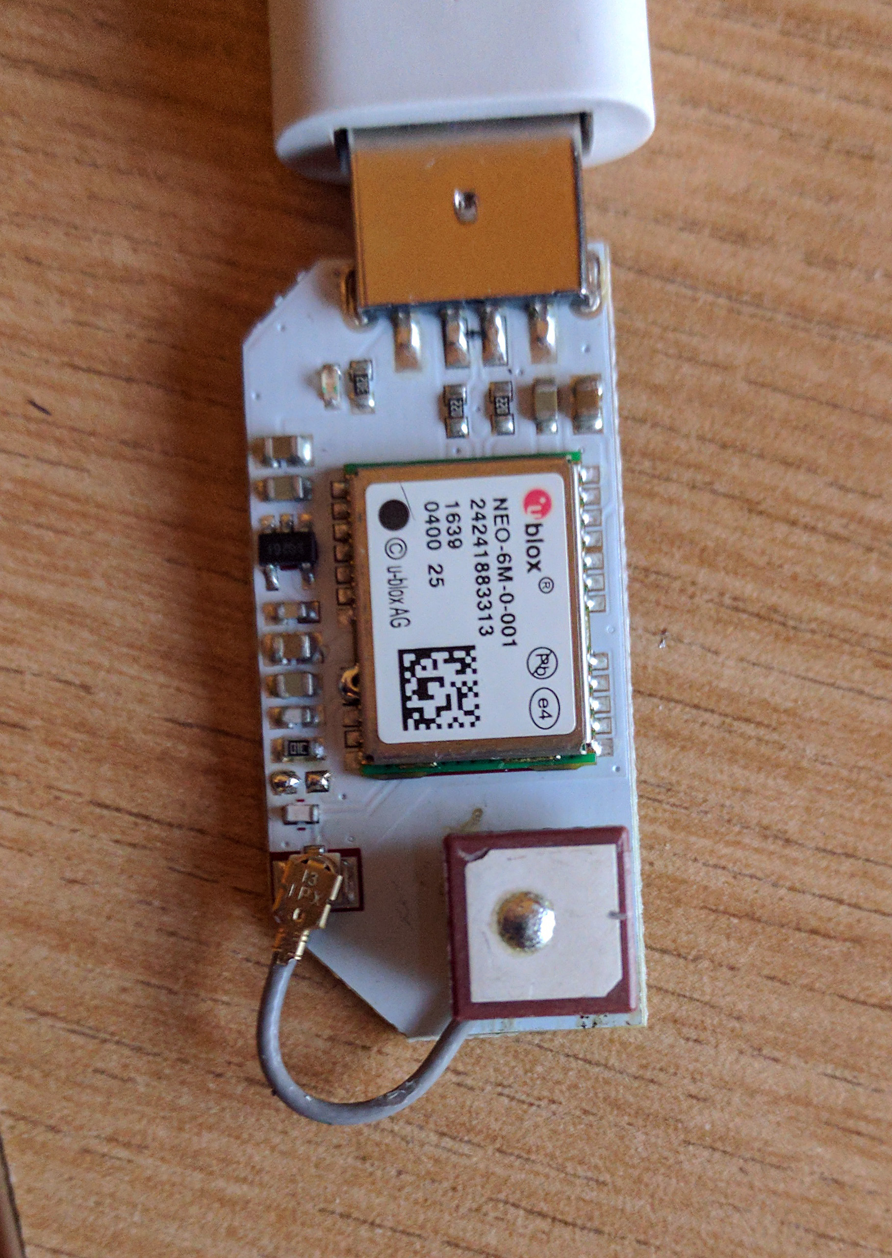
@Douglas-Kryder the other thing I did that may be notable, after desoldering the antenna from the PCB, is clearing excess solder from the antenna left over from when it was originally soldered to the PCB. In particular, one corner of the LNA shield (on the bottom of the antenna) is cut-away, but when it was soldered to the PCB, this corner was filled with solder and shorted to a pad/via on the LNA board. I cleared that on all of my 3 GPS Exps as part of the R&R and did not re-fill it when re-mounting the antenna. Given the shield is cut-away there, I believe it's not meant to short to the pad and this may be deafening the LNA.
-
RE: gps receiver not lockingposted in Omega Talk
@Dana-Myers114 I may have had a breakthrough with the GPS sensitivity issue. In the course of tinkering with my GPS receivers (removing the antennas, inspecting them, etc.) I found that sensitivity appears to be restored if you re-route the coax pigtail from the antenna so that it's not over the PCB:

This appears to reliably fix every one of my 3 GPS EXPs. I did desolder/resolver the antenna in each case before discovering this, but I don't think that's necessary - I think you may be able to fix your GPS by removing the pigtail from the U.FL connector on the PCB, re-route it, and replace it on the U.FL.
If you can try this and report back, I'm curious to hear how it works for you.
(I think this has to do with the cable/connector being too close to the input component on the PCB but that's speculation).
Dana
-
RE: Using a MCP3008 via SPIposted in Omega Talk
@WereCatf yeah I suppose one could install it and it might even work

-
RE: Using a MCP3008 via SPIposted in Omega Talk
@WereCatf the only SPI package in b160:
unless I'm mistaken.
I suppose one could install it with opkg.
-
RE: gps receiver not lockingposted in Omega Talk
My GPS receiver won't lock with the built-in antenna; I connected it to my Pixel phone USB port, started up Droid Term, and immediately saw the NMEA strings - good. However, no fix, just a lot of commas. So then I plugged in my external antenna/LNA and almost immediately got a fix. My board has a blank component location in the second spot from the U.FL connector - if I understand correctly, this is where the capacitor that needs to be removed was and is thus already removed.
Certainly not useful without a remote antenna - makes me think the built-in antenna is not functioning correctly.
-
RE: Using a MCP3008 via SPIposted in Omega Talk
@Pierre-Rossinès doing bit-banged SPI I/O would mean rebuilding the firmware image anyway, so you might as well just build the firmware with the patch (which is what I did). I'm building LEDE trunk with the addition of the Onion feed; the one real trick is to include the RAlink wifi driver from the onion feed and deselect all of the LEDE trunk wifi drivers. I can send you my SPI patch (derived from berniwa's patch and similar to @WereCatf) and .config file if you're interested.
-
RE: SPI Pins for the Omega2posted in Omega Talk
@WereCatf presumably you've already confirmed the clock phase and polarity requirements of the display and that the MT7688 SPI is correctly configured? Are the other SBCs running the same bits (other than the SPI driver)?
-
RE: TFT screen via SPI not workingposted in Omega Talk
@at there are bugs in the SPI support - I suggest looking at this forum thread for background:
https://community.onion.io/topic/1560/spi-pins-for-the-omega2/30
The summary answer is: you probably should try @WereCatf 's firmware image.
(However, I expect spi-tool write 0x12 0x42 to correctly send 0x12 0x42 to the device, so it might be something else)
-
RE: SPI Pins for the Omega2posted in Omega Talk
@WereCatf I generated my own build (LEDE + Onion feed), incorporated berniwa's patch to spi-mt7621, and am pleased to report it's working for me so far (testing with both spi-test and pyOnionSpi). My SPI slave target is an Atmel ATmega1284P and I'm validating the behavior in the ATmega using a JTAG debugger.
I also flashed an O2+ with your provided image, and verified it with spi-tool. Of course, both of our patches include this warning:
             if (t->tx_buf && t->rx_buf) {
                    printk(KERN_ERR
                        "The MT7621-SPI does not support full"
                        " bidirectional SPI, only doing TX!");
            }
which generates arguably gratuitous chatter and probably ought to be removed (I'm removing it from my version of the patch).
I also validated larger than 16-byte transfers work correctly (I tested writes, since my slave device is currently very simple and doesn't talk back yet).
Pending a bit more testing, this patch seems like it ought to back upstream - would you consider doing the PR?
Thanks for the help!
-
RE: SPI Pins for the Omega2posted in Omega Talk
@WereCatf OK - I may actually get test bits tonight and report back. SPI slave target is an Atmel AVR (ATmega1284P at the moment, but I'll be shifting to an ATmega328PB as soon as SPI functionality is verified, though that really makes no difference).
Assuming the patch works - I suppose it's begging to be a pull request upstream, really rather not maintain my own fork of the base OS.
Thanks again.
-
RE: SPI Pins for the Omega2posted in Omega Talk
@WereCatf @WereCatf I'm fixin' to test that patch myself; any hints on generating the LEDE build? I'm rather hoping I can
a) Add the onion feed to feeds.conf.default with this line:
src-git onion https://github.com/OnionIoT/OpenWRT-Packages.git;omega2b) start with .config :
CONFIG_TARGET_ramips=y
CONFIG_TARGET_ramips_mt7688=y
CONFIG_TARGET_ramips_mt7688_DEVICE_omega2=yfollowed by make defconfig
After that, make menuconfig and select spi-tool + Python lib, then sysupgrade my test target. Is there any reason '-n' is required in the sysupgrade? I have a serial console anyway but I figure a regular sysupgrade ought to work OK if I make sure to include the Mediatek SoftAP driver from the onion feed.
Once I establish the baseline build works, I'll drop in the patched spi-mt7621.c source and
spin it.Any hints?
-
RE: Spi interface. How does it work?posted in Projects
@WereCatf I was looking for the patch itself to see how it compares with what I came up with.
-
RE: SPI Pins for the Omega2posted in Omega Talk
@WereCatf Which patch did you use? I'm integrating and unit-testing the patch I found in the Mediatek Labs forum; same one?
-
RE: Spi interface. How does it work?posted in Projects
@Lazar-Demin have you been following the other Omega2 forum thread on SPI behavior? There are two problems:
-
- Upstream OpenWRT/LEDE driver for the MT76xx SPI (spi-mt7621.c) needs a work-around for a bug in the MT76xx SPI - loses MSB of first byte in transfer
- 1a. The upstream driver really needs to process transfers greater than 16 bytes (hardware limitation of MT76xx SPI) in chunks of 16 bytes in the driver. Right now the driver returns an error for a transfer larger then 16 bytes.
Ideally a patch for the driver is required; one such patch has been provided on the MT7688 forum at Mediatek Labs.
-
-
RE: SPI Pins for the Omega2posted in Omega Talk
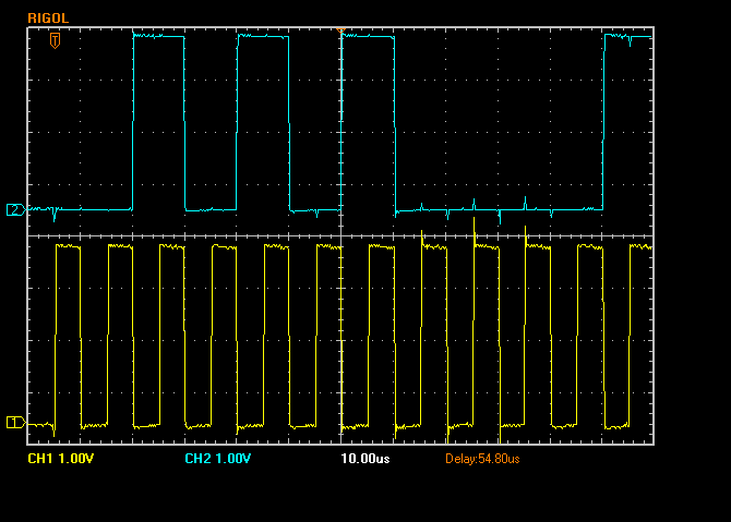
So here's a capture of CLK and MOSI from "spi-tool write 0xaa 0x11":

Upper trace is MOSI, lower trace is CLK, aligned to the vertical grid (10uS). You see the CLK leading-edge transitions are in the middle of the data - it all looks right except the first '1' bit is missing (far left, the first clock transition occurs while MOSI is 0).
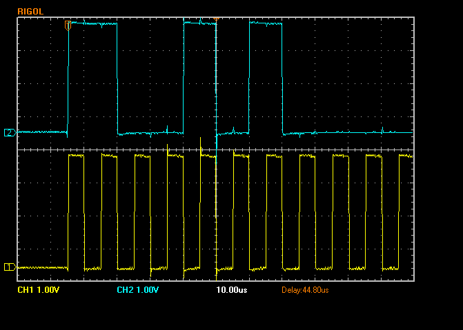
This is "spi-tool write 0xca 0x11":

So here, MOSI starts with an abbreviated '1' bit, only about 1/2 as long as it should be, though the rest of the data timing is correct.
There are two problems:
- list itemWhen the first two bits are '10', the leading '1' is completely not sent by the SPI peripheral.
- list itemWhen the first two bits are '11', the leading '1' is about half as long as it should be.
This makes me think something is amiss with the SPI peripheral - perhaps some timing in the MT7621 SPI driver?
-
RE: SPI Pins for the Omega2posted in Omega Talk
@James-Behrens as you probably have seen in my messages; the Omega Python library needs to break up the SPI transfer into 16-byte chunks and chain them together in the SPI_IOC_MESSAGE() call - I think that'll solve the transfer limitation. The loss of the MSB in the first byte (aka address) happens when the top two bits are '10' and not when they're '11' and that's apparently something in the MT7688 SPI driver and/or timing of the SPI slave.
-
RE: SPI Pins for the Omega2posted in Omega Talk
So - about the leading bit of 'address' (which is not a pure SPI construct - there's no requirement for an address to be the first byte of a transfer, or even for transfers to be in bytes). On a hunch, I tried values of address with the top two bits being '10' (example, 0xaa, 0xb2, 0x88, etc.) and values of address with the top two bits being '11' (ex. 0xc0, 0xff, etc.) and found that anything with '10' in the top two bits loses the MSB (transfers it as '0') and anything with '11' in the top two bits transfers it correctly. My test hardware SPI slave is an Atmel ATmega1284P , with the clock phase/polarity set to 0 (which matches the default settings in the Linux driver) (any other settings in the AVR SPI slave corrupt the data). I tried reducing the clock rate and adding a delay but never helped.
So I'm guessing there's a timing/phase issue there; I'll have to get the oscilloscope out and have a look.