My Omega 2/2+ dock\new
-
@Me-Too i would add to the discussion that the boards come in 3-packs for ~ $9US. it might be easier if you use solder paste for some of the components, put a adequate amount on the pad and place the piece then use either a soldering iron or hot air or in a pinch put it into a heated oven i suppose (never done it) if you do the oven you might want to mount all pieces first. otherwise you will be reheating the solder multiple times on some components and i'm not sure if that is best thing to do. my order is waiting on osh park getting a full panel so if you order soon it might help us all get the boards quicker.
")
-
Guys-you're great!
Yes, @valerionew, you're right that I asked in both places. I created a gist before I found this, and decided it might be useful to have it here, too. Thank you so much for the answer and listing the equipment you have! I doubt I'll buy what you have (sometimes I'm cheap about the wrong things, but I won't use these very much), but it's great to see the actual equipment to see if what I have might suffice.
My fear of SMD is due to previous experience where the contacts and pads were completely obscured by the part. That made baking (which I read an article once about doing smd that way) or possibly hot-air, but only sometimes on the air.
@Douglas-Kryder Thanks to you too...the solder paste seems like a great, and easier idea, even though I've never used it. I'm glad it's 3 packs, so I can still get 2 if I screw up the first attempt!
Oh, and I'm placing the order now, so maybe that will help get them quicker.
Mike
-
@Allnight , forgot to mention that there are many videos on youtube that show methods of smd soldering.
-
By the way i checked the ethernet speed with iperf. Seems good to me. (94.4Mbit/s up and down, in case the image doesn't work)
I'm using a 0.1uF instead of 1uF capacitor to ground the center tap of the transformer, but i don't think that's significant. If you happen to have a 0.1uF 0805 capacitor instead of 1uF, don't bother buying a 1uF one.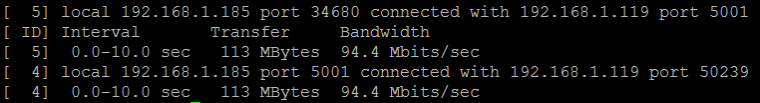
-
FYI...I just got a from OSHPark that my order is in fab right now. It says there are 81 other orders for a total of 543 boards on this panel. That is pretty cool!
-
i need a bit of help/advice. i was looking for the ethernet jack in u.s. and the exact part# given in bom it seems is only marketed in europe. so i did some searching at digikey , had a few picked out & bought what i thought was close. turns out what i was sent has the lights. so, 2 questions,
- is there a way to get lights to work?
- is it ok to drill holes for the pins?
as far as function of the 2 pins i'm guessing they are + & ground for power to the lights. this would be a nice feature to have if possible. thanks in advance for any comments someone may have on this issue.
-
@Douglas-Kryder said in My Omega 2/2+ dock\new:
- is there a way to get lights to work?
No, the right pins are not wired out from the chip.
On the Omega2S, as reported here, they are, but unfortunately not on the Omega2/2+.- is it ok to drill holes for the pins?
as far as function of the 2 pins i'm guessing they are + & ground for power to the lights. this would be a nice feature to have if possible. thanks in advance for any comments someone may have on this issue.
I wouldn't suggest that, because top plane is +3.3V, bottom ground plane is ground. There's a big risk of making a short on the power if some pin somehow touches exposed copper on top and bottom.
I suggest you to snip them off, as close as possible to the plastic case
Anyway i'll consider making some holes (not connected) in the project, in future versions
-
Do you plan to offer these commercially (assembled)? They would fit perfectly for a project I am working on.
-
@valerionew ok, thanks for the information. my boards arrived today so i pick them up Monday from post office and begin assembly. did you have to perform any kind of setup for this ethernet board like described on this page for the onion eth expansion?
https://docs.onion.io/omega2-docs/using-ethernet-expansion.html#using-ethernet-expansion
-
@Razvan-Dragomirescu said in My Omega 2/2+ dock\new:
Do you plan to offer these commercially (assembled)? They would fit perfectly for a project I am working on.
Currently i'm not planning to. I can make one or two boards for who can't solder it's own, but for the moment i'm not planning anything commercial.
If you need some production beyond that you can do it, the license allows it. If some commercial production is made, any donations will be appreciated.@Douglas-Kryder said in My Omega 2/2+ dock\new:
@valerionew ok, thanks for the information. my boards arrived today so i pick them up Monday from post office and begin assembly. did you have to perform any kind of setup for this ethernet board like described on this page for the onion eth expansion?
https://docs.onion.io/omega2-docs/using-ethernet-expansion.html#using-ethernet-expansionCool! Pretty quick in the US! In Europe usually i need to wait about 20 days.
Moving on, i've done a lot of tests troubleshooting the ethernet in the previous version, so i can't remember exactly if i've done any extra configuration. For what i can remeber, the only configuration that was needed, was the first point of that guide. Currently in my/etc/config/networki have this:config interface 'wan' option ifname 'eth0' option proto 'dhcp'So modify/add that and don't forget to restart the daemon:
/etc/init.d/network restartIf everything is working correctly, you'll se something like this on the dmesg when you connect the cable:
rt3050-esw 10110000.esw: link changed 0x01;
You'll be able to see the eth0 local ip withifconfig;
And you'll be able to ping anything on the internet withping -I eth0 [address].Let me know!
-
I thought that people might be interested to hear that I just received my boards from OSHPark. Hopefully that means that everyone waiting for orders will get theirs any day now, as well.
So, now I need to pull together the components and then assemble them!
Mike
-
@Allnight keep me updated, if you need any help!
@Douglas-Kryder how is it going with your board?
-
@valerionew hi, as sometimes happens in my life, unexpected stuff happens that kills my "fun " time that i use for projects. so , looking to get started saturday on my board, i have all parts. thanks.
edit: saturday, got started on board and first time i looked at it up close wanted to ask about that what appears to be a near bridge between pins on micro ab-usb [D+,D-] power-in, is that something you wanted.
edit: sunday, i have read it may have something to do with a signial to the power supply about device needing just power. turns out the micro ab power-in receptacle you had selected has a different footprint than what i had so i ordered a correct one and will have it this friday to complete board.
-
@valerionew i need some help on polarity on the pcb for C3, C4 , C5, F1, & D1. i don't see any markings on the board i'm familiar with. i never have been any good at getting placement info from schematic. thanks.
-
@Douglas-Kryder Sure.
C3, C4, C5 are ceramic capacitors. They are not polarized, so you can put them in either way.
F1 is a PTC, basically a resistor that changes it's resistance according to the temperature, and it is non-polarized too.
D1 is a LED, so it is polarized. Anode and cathode should be marked on your led. Some of the most common markings are shown here (https://goo.gl/images/WXHRK8). In the dock\new, the cathode (negative) side of the LED is facing towards the edge of the board (to the right in this picture)
-
@valerionew said in My Omega 2/2+ dock\new:
@Douglas-Kryder Sure.
C3, C4, C5 are ceramic capacitors. They are not polarized, so you can put them in either way.
F1 is a PTC, basically a resistor that changes it's resistance according to the temperature, and it is non-polarized too.
D1 is a LED, so it is polarized. Anode and cathode should be marked on your led. Some of the most common markings are shown here (https://goo.gl/images/WXHRK8). In the dock\new, the cathode (negative) side of the LED is facing towards the edge of the board (to the right in this picture)ok, just one double check. and this one i almost solder in place, but D1 has a small green dot [on my LED it has green marking on same side as cathode marking on underside] on side facing away from edge. does that green dot on LED have any significance ? thanks.
-
@Douglas-Kryder Yes the green dot is the cathode, my mistake with the picture. I'll fix that in a moment (although it will need some time for the github's internal cache to reload).
Green dot should be facing the edge.
EDIT: doing some research, the dot can either indicate the anode or the cathode.
When in doubt, better test the led with a multimeter in the "diode test" mode.
Otherwise, referring to the datasheet seems a good idea, if you have a part number
-
@valerionew ok, thank you for the speedy reply and the info.
-
@Douglas-Kryder said in My Omega 2/2+ dock\new:
@valerionew, i completed populating the board. the regulator is warm to touch however the power led does not light up. when i tried with omega2+ in headers there was also no power led on the omega2+. so, do you have any suggestion or tips on debugging what appears to be an issue with my power circuit? thanks.
-
@Douglas-Kryder
Can you post some photos of the component side?
After plugging the usb you should measure the voltage on the regulator's pinsBTW don't insert the omega in the dock again before we resolve this power supply issue.