Pinouts for Omega, docks, and expansions
-
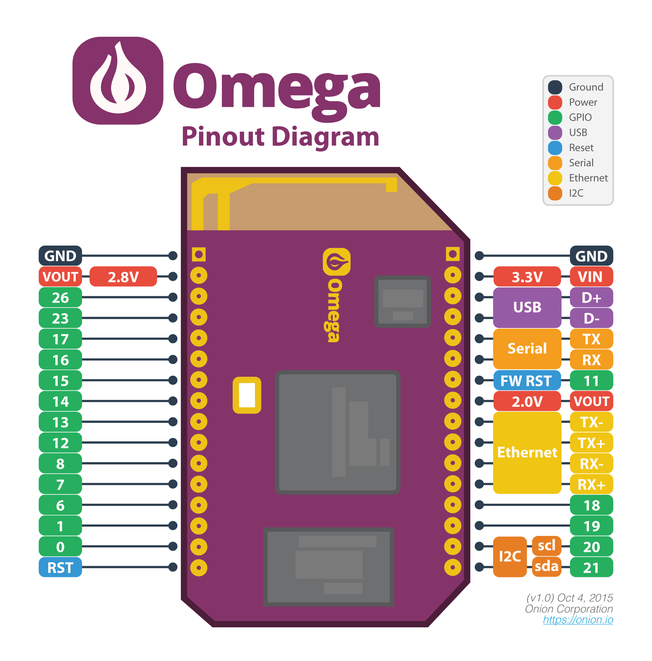
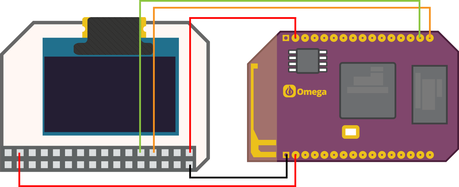
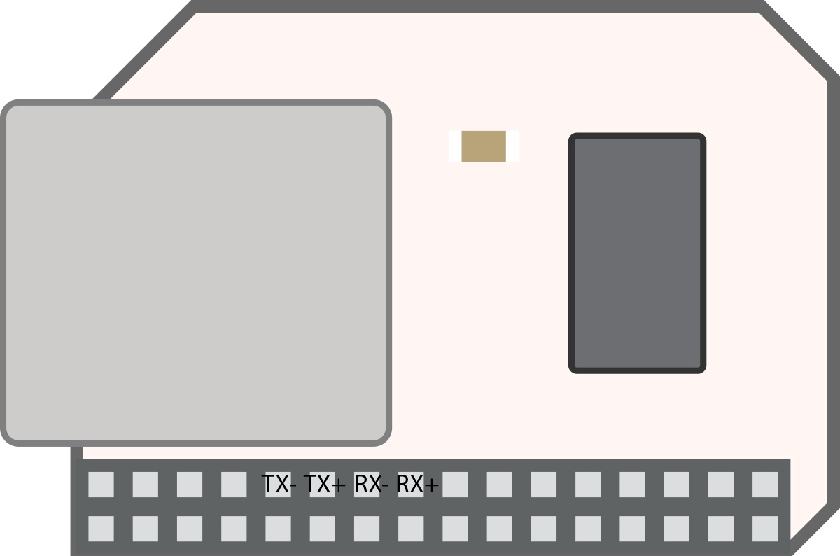
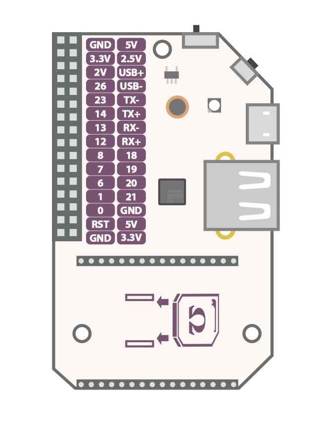
I haven't seen a page that has all of the pinout diagrams for the various components in one place. Am I just missing a page on the wiki somewhere?
In the meantime I'll start dropping them into this thread as I imagine I'm not the only one who would like them all in one place.
 If there are some I'm missing please feel free to add them!
-
Omega pinout

-
OLED display pinout

-
Ethernet pinout

-
Expansion dock

-
@fader That's a great idea. I'll add that to our Wiki now.

-
Does anyone know what voltage/amp the GPIO pins give when on output?
-
Found this from Boken Lin:
The voltage on the Omega is 2.7v. 0 is ground, and 1 is 2.7v. Yes, you can take these voltages directly from the Omega.
-
@Nicolas-Hampton Max current on the GPIO is around 20mA.
-
@Boken-Lin Is there any reason that comes to your mind that using Pin 14 as In on a Button makes the Omega unbootable.
LED on expansion board just goes on for 10ms or so... than off again.When using Pin 13 everything is fine without changing my circuit.
Cheers Ben
-
@Benjamin-Rau I have just had a play with my Omega and pins 13 and 14 when set as input both operate equally and as expected.
Unless there is a problem with my Omega, there are a few things you could check (forgive me if these are obvious to you or you have already done them :-)):
- Are you sure that the circuitry is the same for 13 and 14?
- Is the code used to access each of 13 and 14 the same?
- Is there anything else that is using one pin but not the other?
- If you are using mechanical switches to control the pins, do you have a suitable pull-up/pull-down resistor to pull the pins to the appropriate state when the switch is open?
- If you are using mechanical switches, do you have suitable de-bounce circuitry to account for noise? A capacitor in parallel with the switch (along with the use of pull-up/pull-down resistors) should handle this