Omega 2S+ VDD_FLASH pin
-
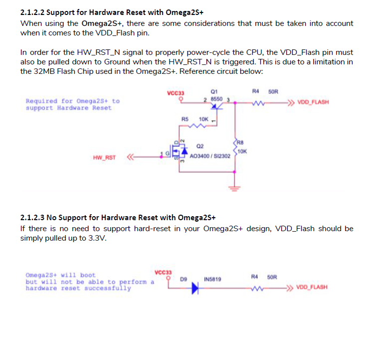
On the Omega 2S+ can I connect the VDD_FLASH pin directly to 3V3? Or is the series diode and 50 ohm resistor required? I don't need hardware reset.
-
@SimonPR If the datasheet specifies a configuration, it is best to follow it
In both configurations they add the 50 ohm resistance, I would think that it is limiting the current that reaches the VDD flash pin, but it may have other critical reasons related to the correct functioning of the Omega
-
@SimonPR @jossvall Is correct. The datasheet specifies the design recommended by Onion Corporation, deviate from it at your own risk.
-
@crispyoz @jossval Yes I totally agree re following the recommendations, and it's what I'll do for now.
Was hoping to get a bit more detail on the exact implications of just connecting it to 3V3 (eg backflow and excess supply current risks).
I just really don't want to add more components if I can help it!
-
@SimonPR this would be a question for one of the Onion engineers, however the Onion team are pretty fastitious engineers, so if they say you need it, then you need it. I prefer to keep the puff of blue smoke inside my devices rather than release them
")
-
You can directly connect VDD_FLASH to +3.3V. I have >1000 24/7 working devices in the field that are wired like this, so I'm quite confident
")
The reason for having that pin separate is that if you find yourself in a situation where you need to directly re-flash the SPI flash chip (e.g. after a failed attempt to update uboot), you can apply power via VDD_FLASH to the SPI flash chip without powering the SoC (MT7688).
This allows to re-program the flash using an in-circuit SPI flash programmer. The diode allows this without changing anything on the board (no jumpers required). I guess the 50Ω resistor is there for noise reduction.If you wire VDD_FLASH to 3.3V directly, there's no way (except cutting traces on the PCB or unsoldering) to get a ruined uboot re-flashed. For my devices, I decided I will never touch uboot once they are produced…
The HW reset thing is another story - this extra circuit is needed to make the SPI flash reset (by interrupting its power supply during HW_RST) to ensure the address mode is right for the MT7688's startup.
If I recall the details correctly, address mode needs to be 3-byte during boot, but the firmware might later switch it to 4-byte. If then a reset occurs, the SPI chip is in 4-byte mode and the MT7688 tries to boot with 3-byte, which fails and leaves the device inoperable until power-cycled.