Simple Python wrapper and demo
-
@Nick-Bonifacio Ah, oops I meant for that to be "gpiohelper.py" rather than "pyhelper.py"! Have updated my original post.
I'm not really a Python coder myself so no idea if putting stuff in
/usr/bin/python2.7/importlibis best practice or not. But if it works it works!

-
@Dan-L I don't think it is best practice haha. Hopefully, someone will chime in and tell us where it goes. What did you end up doing with it?
-
I just had both files as:
/root/test/gpiohelper.py
/root/test/gpiotest.pyWritten directly with Nano

-
@Dan-L. : thanks for sharing.
how have you connected the LEDs? do you use any pull-up resistors or do you go directly from IO-pin to GND?
thanks!!
-
Thanks @Dan-L Will give the Arduino Dock a go tonight and maybe will manage to figure it out.
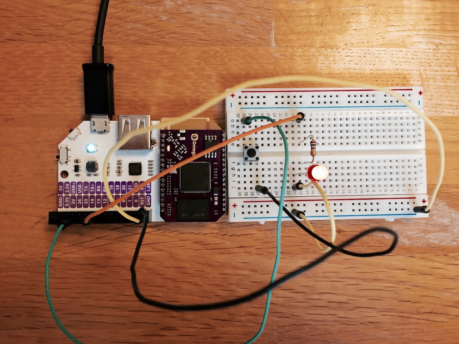
@gosch I have attached a photo of how I connected one LED (led pin 13) with one button (button pin 26) and used @Dan-L code to get it to work.
-
Hi @gosch, I started off with this.
Basically connecting a GPIO pin to a 330ohm resister, then the resister to the LED (longer leg), then the LED to ground. For my example code though, I was using 6 LEDs with 6 resisters, with the ground pin of each chained together and linked to a single ground pin on my expansion dock.
I also set up a button using an Arduino guide I found here.

-
Nice one @Romans-Bermans!
-
@Romans-Bermans: thanks for the picture!
@Dan L.: thanks for the info & links!
-
Hey @Dan-L , finally got some components to play around with!
Although I'm getting the following error when trying to read the input of a button using your helper,
fast-gpio read 8works perfectly though, any ideas?Traceback (most recent call last): File "script", line 19, in <module> button_input = helper.getPin(8) File "/root/first_script/gpiohelper.py", line 26, in getPin fd = open(self.pinDirectionPath.replace("$", str(pin)), 'w') IOError: [Errno 13] Permission denied: '/sys/class/gpio/gpio8/direction'
-
@Jamie-Street Know what? I have the same problem with pin 8. If you try a different pin does it work?
I also have trouble with pin 13, but it doesn't actually give errors, it just doesn't do anything.
-
BTW You can test easily with the command line too.
echo out > /sys/class/gpio/gpio5/direction
echo 1 > /sys/class/gpio/gpio5/valueecho in > /sys/class/gpio/gpio6/direction
cat /sys/class/gpio/gpio6/value
-
Cheers for the heads up, upon inspection it looks like the
directionfile is missing for pin 8, pretty strange.. perhaps the helper should create the file if it doesn't already exist?
-
@Jamie-Street The helper doesn't specifically create those files individually, it triggers the export functionality. I'd say it's a bug with the Omega firmware...
-
@Dan-L @Romans-Bermans we're still working on the drivers for the Arduino Dock, its a little more complicated than we anticipated. Should be out soon tho!
As for pin 8, I'll be looking into that, we might have made it output only for some reason. I'll double check.
-
Thanks for the clear example.
Is there a reason I can't access pins 15-17 (extension board RGB led)?
I can update the values using (b)ash fast-gpio commandsroot@Omega1:~# ls /sys/class/gpio/
export gpio1 gpio13 gpio18 gpio23 gpio6 gpio8 unexport gpio0 gpio12 gpio14 gpio19 gpio26 gpio7 gpiochip0
-
@Dan-L. Thank you for sharing that implementation.
I used your implementation, then added support for pin 8 ( via fast-gpio ). I also set it up so it could run on my mac in a simulated way.
Here is a link to a video showing it all work.
https://www.youtube.com/watch?v=jDDq9D50wGo
Thanks gain
-
@Romans-Bermans So for the pushbutton, how is that wired? It's hard to tell from the photo. It looks like the green leg is connected to 2V and the black leg is connected to RST? Please confirm. Thanks!
-
@Steve-Fister Probably not. Reading the code the button is connected to pin 26, the other side probably is connected to +5V. Although this might work, it is good practice to also connect a resistor (like 10kOhm) between pin 26 and ground, to ensure pin 26 is at 0V when the button is NOT pushed.
-
@Peter-Peters Logic voltage on the Omega is 2.8V. So the other side should be connected to 2.8V.
-
Woops, my bad.., but in that case the picture also shows the wrong connection...
What do you actually mean by 'logic voltage'? Is that the level where a '1' is detected or
the max input voltage for digital inputs?So which of other 3 possible pins is the right one then? 2V, 2.5V, or 3V?
Or maybe the Onion Omega has a similar 'internal pullup' construct like the Arduino? In that
case you just change the circuit such that the button pulls 'down'.