Omega2 DIY Mega Expansion Dock
-
Hello!
I'm just created my own expension dock. It's contains the following:
1. USB host;
2. USB device;
3. Ethernet;
4. ON/OFF switch with power indicator;
5. Resset Button;
6. 1 User LED and 1 User Button.3D view
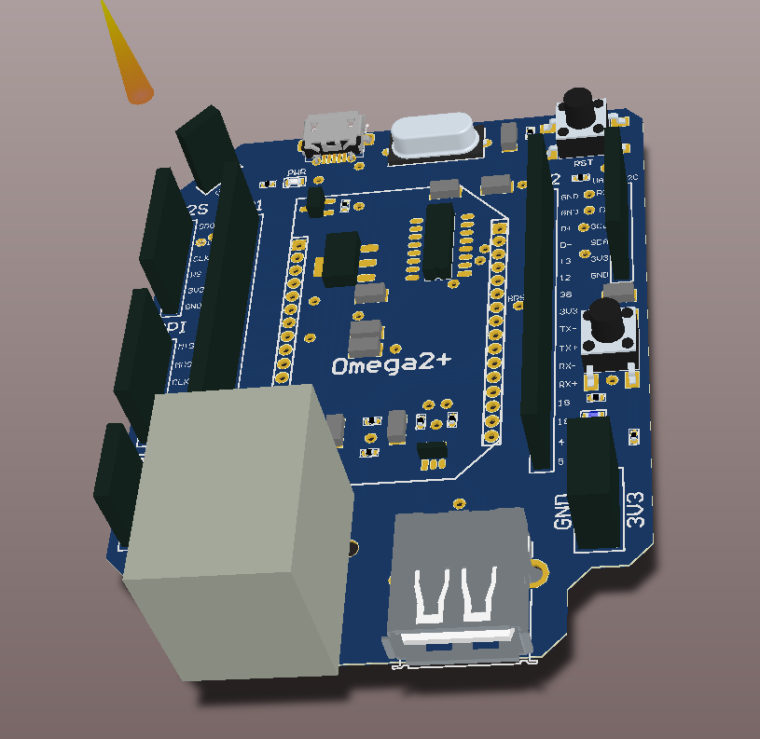
Top View
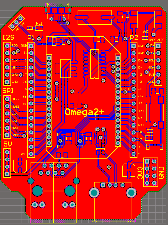
Bottom View
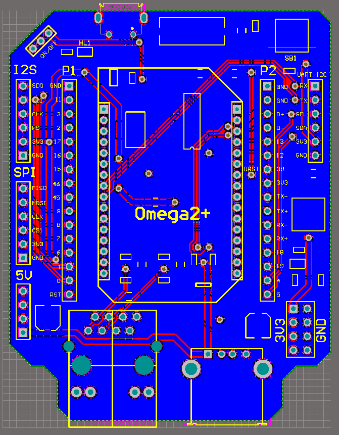
It has on onboard linear voltage regulator (3.3 v), ESD protection scheme, CH340G USB-UART converter. Also it has GPIO Headers and individual Headers for I2S, SPI, UART/I2C and 3.3V/5V/GND. All components you can see on the Scheme:
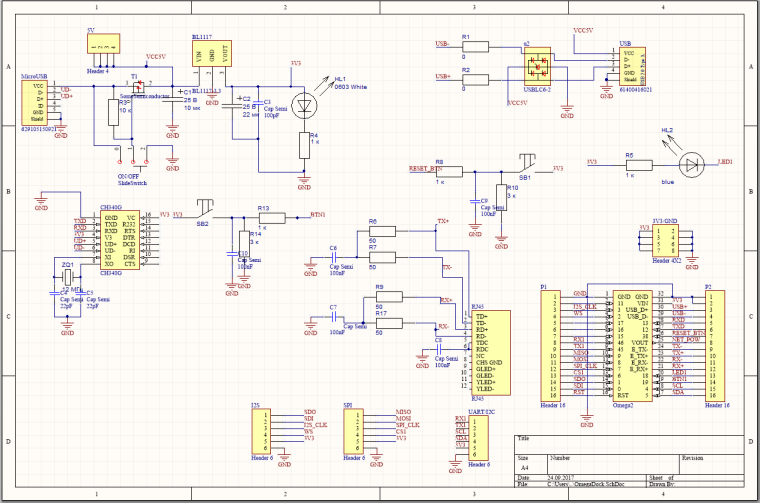
Altium project and libs you can find on the GitHub rep.
Please, let me know if I have missed out anything.
UPD: Added new capacitors.
-
Nice job indeed.
I only miss some 100nF decoupling capacitors around every local power supply pin. I see only some 100pF capacitors there.
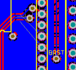
Can you explain these - maybe unconnected - lines?
Regards,
Gyozo
-
@Gyozo-Nemes Thank you very much! It really was unconnected. I updated screenshots and project.
-
@Ilya-Maksimovich
C1, C2 22pF and C3 100pF are probably some typo.The RESET_BTN input is a "simple" active high GPIO input (FW_RST).
You may connect it directly to the +3.3V via a normally open momentary push button.I don't fully understand what is your intention with those R-C network between a push button and a digital input:
3.3V - SB1 - R8, R10, C9 - RESET_BTN input
3.3V - SB2 - R13, R14, C10 - BTN1 (GPIO input?)
-
@György-Farkas
The values of resistors and capacitors were taken from the extension dock of omega2. Include voltage divisors on the buttons. I just added capacitors to avoid button bounce.
-
@György-Farkas
About capacitors on the voltage regulator.
Power supply only from the USB. So we can use the low value capacitors for suppressing low noise.
-
@Ilya-Maksimovich said in Omega2 DIY Mega Expansion Dock:
@György-Farkas
About capacitors on the voltage regulator.
Power supply only from the USB. So we can use the low value capacitors for suppressing low noise.No, that's a serious failure of understanding.
Your capacitors are orders of magnitude too small. You should have at least a 0.1 uF (that's 100000 pF) on each side of the regulator for stability. And you probably want at least a footprint to have the option of installing tens to hundreds of microfarads on the board as a local reservoir of charge for demand peaks. The data sheet for the specific regulator variant you appear to have chosen recommends 10 uF on each side.
The picofarad capacitors you have used would at most help avoid putting radio frequency noise back up the cable to radiate as an antenna - but probably not even with that.
-
@Chris-Stratton
Ok. I understood. I'll update scheme soon.
-
They are stabilizing capacitors, not just for decoupling.
LT1117-3.3 needs 10uF input side and 22uF output side.
Use an even larger cap to address inrush current, you won't regret it.
(I used a 470uF on output side...)
-
@ccs-hello thx. I fixed this.
-
This post is deleted!