Momentary Switch Circuit for Omega2
-
So, I don't think that circuit is going to do what you want.
I see you have a voltage divider comprised of 51K and 5.1k.
What will happen is the higher GPIO input resistance makes it possible for much higher then 3.3v to be present at the GPIO pin, especially when no current is flowing.
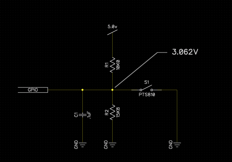
What you want to do is create a voltage divider to ground configured in such a way that the voltage to the pin will never exceed 3.3v, but really anything over 2.8v is good enough.
Something more like this drawing.
Also, take care with the pins you hook up to, many of the GPIO need to be left floating at boot.
It might make more sense to use a MCP23008 DIO expander to monitor the inputs instead of direct to the Onion.
-
@Jeff-Seese
Onion Omega2 Arduino Dock Starter Kit
...Reading a Push Button
......Debouncing Switches
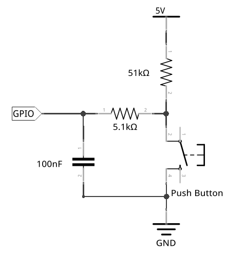
Originally that GPIO was an ATmega328P pin.That two resistors are not a voltage divider. The 5.1 kOhm is a current limiter.
As you know the GPIOs of Omega2 are not 5 V tolerant but - with this circuit - Omega2 most probably will not damage (immediately ;-).
OP should connect the 51 kOhm resistor to 3.3 V.
-
@Roger-Sinasohn There are only seven (7) "free" GPIO Inputs on the Expansion Dock's Expansion Header for this circuit.
Using the Omega’s GPIOs
After the next commands you can use GPIO 0, 2, 3, 6, 18, 19, 46.
omega2-ctrl gpiomux set uart1 gpio
omega2-ctrl gpiomux set spi_cs1 gpio# Omega2+ FW v0.3.2 b218 root@Omega-5BE1:/# omega2-ctrl gpiomux set uart1 gpio set gpiomux uart1 -> gpio root@Omega-5BE1:/# omega2-ctrl gpiomux set spi_cs1 gpio set gpiomux spi_cs1 -> gpio root@Omega-5BE1:/# omega2-ctrl gpiomux get Group i2c - [i2c] gpio Group uart0 - [uart] gpio Group uart1 - uart [gpio] pwm01 (*GPIO45), GPIO46 Group uart2 - [uart] gpio pwm23 Group pwm0 - pwm [gpio] GPIO18 Group pwm1 - pwm [gpio] GPIO19 Group refclk - refclk [gpio] Group spi_s - spi_s [gpio] pwm01_uart2 Group spi_cs1 - spi_cs1 [gpio] refclk GPIO6 Group i2s - i2s [gpio] pcm GPIO0, GPIO2, GPIO3 Group ephy - [ephy] gpio Group wled - wled [gpio]I was planning on using pins 0-3 and 6-9 on the expansion dock as they aren't labelled as anything else -- will that work?
Sorry, I don't understand this.
Expansion Dock's
Expansion Header pinout (top view)

                +-----+
           GND  | 1  2|
          3.3V  | 3  4|
                | 5  6|
         GPIO3  | 7  8|
         GPIO2  | 9 10|
(RX1)   GPIO46  |11 12|
(TX1) (*GPIO45) |13 14|
                |15 16|
                |17 18|  GPIO18
                |19 20|  GPIO19
         GPIO6  |21 22|
                |23 24|
         GPIO0  |25 26|  GND
                |27 28|
           GND  |29 30|  3.3V
                +-----+

* GPIO45 already has a 4.7 kOhm pullup resistor under the shielding
Be careful!
The GPIO's of Omega2(+) are not 5 V tolerant - so you should connect the pullup resistors to 3.3 V.Good luck.
-
Thanks for all the help! Going in reverse order...
@György-Farkas -- I think I meant "GPIO" rather than "pins" when I said "I was planning on using pins 0-3 and 6-9 on the expansion dock". I was referring to the labels next to the expansion header, as seen in this image:
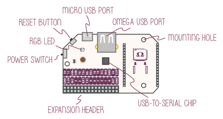
The ones I was looking at are pins 7, 9, 15, 17, 19, 21, 23, and 25. (They're labelled 3, 2, 9, 8, 7, 6, 1, and 0, respectively.)
I take it I can't just use those? I would really like to have 8 inputs if at all possible.
@György-Farkas @Jeff-Seese -- I didn't realize that the circuit I found was meant for the arduino; will it work if I connect it to 3.3v instead of 5v? I think Jeff's circuit is very similar but has different resistor and capacitor values to account for the 5v. Given that the expansion board also has 3.3v available, what values would I need to use?
I apologize for the basic questions; I'm a software guy by trade, where on is on and off is off and there's no ambiguity and nothing in between.
Thanks for the help!
-
I you are using 3.3v then the schematic I sent you will work if you leave out R2.
-
@Roger-Sinasohn You can't use GPIO7, 8, 9 and 1 with this circuit.
GPIO7, 8 and 9 (header pins 19, 17 and 15 respectively) together is the SPI interface - so these pins are mandatory of the system.
GPIO1 (pin 23) has a 4.7kOhm pull-down resistor under the shielding so - using this circuit - this Input is always Low independently of the push button's state.You wrote previously:
... a project that will use 8 momentary switches as input to an Omega2. (I'm using 4 SPDT switches.)
What does '8 momentary sw.' vs. '4 SPDT sw.' mean exactly?
-
@György-Farkas said in Momentary Switch Circuit for Omega2:
You wrote previously:
... a project that will use 8 momentary switches as input to an Omega2. (I'm using 4 SPDT switches.)
What does '8 momentary sw.' vs. '4 SPDT sw.' mean exactly?
Perhaps I didn't word that correctly... I'm using 4 physical switches, each of which, being a SPDT, has two independent logical? switched. That is, push the lever forward, that's one input; pull it back and that's another.
It sounds, however, like I can only have 7 inputs? You mentioned GPIOs 0, 2, 3, 6, 18, 19, and 46. There's no way to get an 8th?
Note: I also want to use the SDA/SCL to hookup an LCD, but I don't think that's a problem.
Thanks for all your help!
Roger
-
@Roger-Sinasohn If I understand well instead the 8 normally open momentary pushbuttons (see the upper layout) you want to use 4 SPDT switches (see the lower layout). Sorry, I can't follow you. Could you explain what do you want to make? More details or a little schematic would be nice.
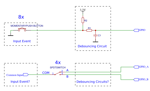
You wrote:I'm using 4 physical switches, each of which, being a SPDT, has two independent logical? switched.
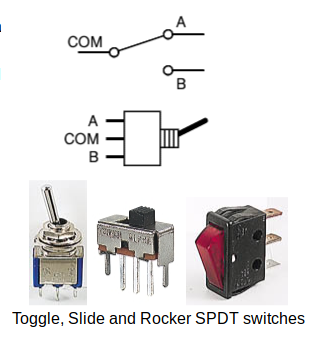
What are you talking about please?
-
I want to have 8 inputs so the user can select one and the onion will note which switch is pressed and display a message accordingly. That is:
if sw1 is pressed then
add 1 to sw1-tally
display "switch 1 was pressed!"
else if sw2 is pressed then
add 1 to sw2-tally
display "switch 2 was pressed!"
. . .
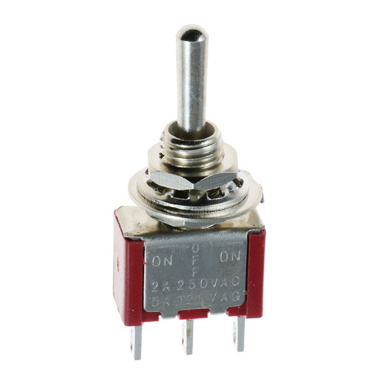
etc.Instead of 8 pushbutton switches, I want to use 4 mom-off-mom SPDT switches such as these:
The toggle switch should be functionally equivalent to 2 pushbuttons. The main different between what I'm using ant the toggle switch you showed is that there is a middle "off" position.
So the schematic is something like this:
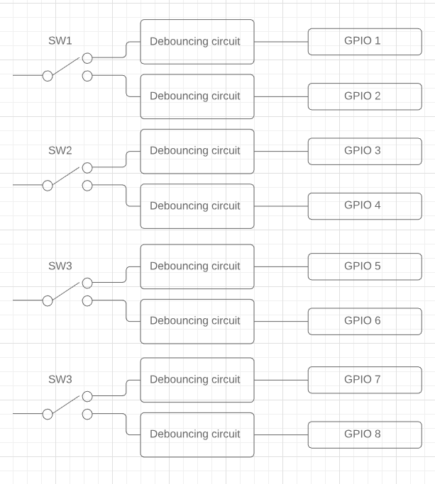
Note that for each of those switched, the normal condition is in the middle, not connected to either output.
-
@Roger-Sinasohn OK. Now I see that you want to use a special momentary (ON)-OFF-(ON) version of the standard SPDT switch.
It has a third switching position in the centre which is off and returns to the central off position when released.About the 8th GPIO:
Omega2(+)'s U-Boot set GPIO11 to Output and High (this is a "secret" hack of Onion guys ;).
With afast-gpio set-input 11command you will get that highly requested 8th GPIO Input - but in this case- the on board RESET BUTTON of the Expansion Dock won't work
- and you can't use Onion's genuine PWM Expansion and OLED Expansion without some little hardware modifications
Maybe I'll write "a few" words about that debouncing circuit... later.
