What does dmesg say?
That image file you're trying may not contain WiFi kernel driver module.
If you post dmesg result, I can tell if WiFi driver is pre-packaged or not.
What does dmesg say?
That image file you're trying may not contain WiFi kernel driver module.
If you post dmesg result, I can tell if WiFi driver is pre-packaged or not.
We were able to use Omega2S on cutom PCB without any hardware problem.
The only issue was SPI driver issue (software issue).
However, we could still use the made custom boards for other purposes and ran well for a long time.
Here's our hardware design repository.
https://github.com/dumtux/omega2-4g-gateway
And this is our PCBA supplier, where we made PCBs.
https://pcbcrew.com
You can add as many vias as you want under the Omega2.
Just avoid placing via on bottom pads, which are used for GND.
An example open-source PCB design is available on pcbcrew-org/omega2-4g-gateway.
It is prototyped and tested in the field by PCBCrew prototyping service.
Thank you @luz
Right now, I gave up solving this MCP2515 issue on OpenWrt 22.03.
We decided to move to ESP32 as the CAN bus was a critical requirement for our projects.
Although this problem is not solved on my side, I hope it could be a little help for people's future projects related to Omega2 + MCP2515.
@luz
I tried p44b build script first of all.
And I got this result.

It seems like the build script doesn't support OpenWrt 22.03 yet.
It totally make sense, as many file locations and contents are updated to kernel 5.10, it would mess if I force to apply all patches globally.
I am now on the way to manually applying the GPIO patch to OpenWrt 22.03.
But it's not easy for me as the gpio-mt7621.c seems like changed.
@luz
I also would like to see your patches as @Gerhard-Bertelsmann said.
Is it somewhere in public repo?
I just did another experiment.
I disconnected external sensor.
Omega2 -> MCP2515 -> (open) -> Oscilloscope
If I enable the CAN bus like this, I can see output CAN packet from the oscilloscope.
ip link set can0 up type can bitrate 125000
cansend can0 01a#112233
Next, I enabled CAN bus with loopback mode.
ip link set can0 down
ip link set can0 up type can bitrate 125000 loopback on
cansend can0 01a#112233
No CAN packet waveform I can see!
To see it again, I should re-enable the CAN bus without loopback mode.
ip link set can0 down
ip link set can0 up type can bitrate 125000 loopback off
cansend can0 01a#112233
Any thought from this loopback mode behavior?
Can you profile digitalWrite function only?
Like this,
 while(1) {
   digitalWrite(PWM_LEFT_PIN,0);
   digitalWrite(PWM_LEFT_PIN,1);
 }
With this code, what's the wavelength of output signal on LEFT_PIN ?
@Gerhard-Bertelsmann
I experienced similar error messages when I used the wrong GPIO number.
For example, I tried this.
interrupts = <75 0x02>
And it gave very similar error as yours on kernel module loading.
As far as I used the right GPIO number 11, the kernel module loading was just successful.
I don't have a clue if this means the issue was eliminated in 22.03.
When I connect two boards via CAN bus, I could only enable CAN driver from one board.
Currently, I am in a different situation after disabling GPIO11's default behavior of the bootloader.
I can enable both side drivers. And each board can send CAN packets by cansend.
However, the interrupt is not invoking and candump still prints nothing.
@crispyoz @Lazar-Demin
Yes, it worked. I choose the omgega2-bootloader instead of omega2p-bootloader accidentally.
After soldering with a brand new Omeba2S+ module, I carefully upgraded bootloader.
Here's the pre-compiled bootloader for others' future reference.
https://github.com/dumtux/omega2-bootloader/releases/tag/tower-bootloader-v0.1
After disabling GPIO11 default behavior from Omega2's bootloader, I could see some different behavior of MCP2515 kernel driver.
I could see some short impulses while initializing MCP2515 driver and enabling can0 interface.
I didn't see such impulses before with the default bootloader.
I'll keep posting further results.
You can use GPIO expanders like MCP23017 and PCA9554.
Take care of using PCA9554, it is cheap but it is reset and all pins are set as pull-up input state on power-up time.
MCP23017 is easier to use as it has no such issue.
@nsmith
I use GPIO11 for CS1, there is no boot issue.
I think it's because the Omega2's bootloader will set the GPIO11 as HIGH output during boot.
Changing device tree cannot help in this case.
Because no matter how you set pull-up or whatever in device tree, the Omega2 need to access flash memory to load the kernel with the defined device tree.
I believe the HW SPI is used after boot.
For example, if you read/write a file in /root directory, it's Flash memory file system operation.
If you read/write a file in /tmp directory, it's RAM virtual file system operation.
When upgrading the OS, I used to upload the system image to /tmp folder as it is super fast.
By default, /root uses internal flash memory.
But you can mount it from an SD card, for example.
Setting Up an SDCARD for /root and swap for Onion Omega2+
I am using the UART1 of Omega2 - /dev/ttyS1 for GPS module communication with 115200bps.
It is 24/7 running for more than 3 weeks constantly.
Working with no error.
So I cannot guess what will be your issue on LTE board.
@Lazar-Demin
How can I build a U-Boot image for Omega2+ ?
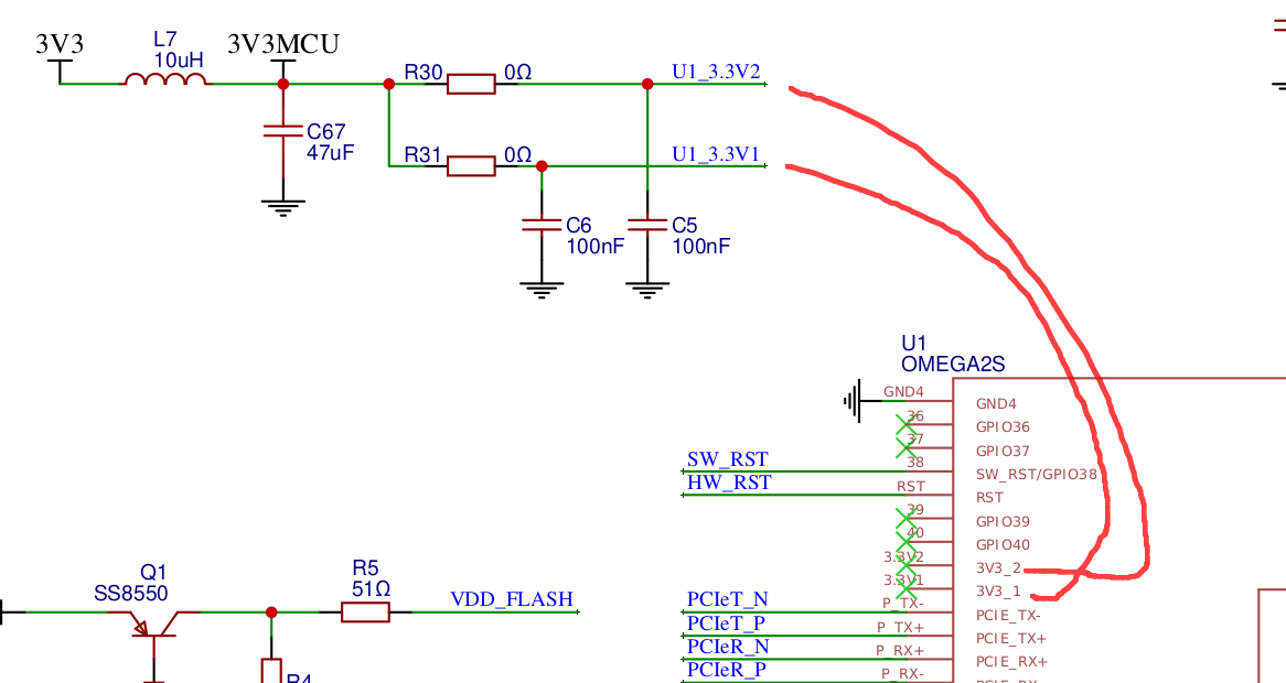
On the schematic, 3V3.1 and 3V32 pins are looking unconnected.
But it is because of a footprint error in the library. I imported the Omega2/2p symbol and footprint lib from SnapEDA and LCEDA was having a problem with net tag names starting with numbers.
If I connect the 3V3.1 and 3V3.2 pins to system power 3.3V, it is recognized as error and I could not route on the PCB editor.
So I let them be unconnected on Schematic and added net tags manually.
Just ignore those 3.3V wiring.
I had to fix the footprint lib, but I had no time to do it at the designing time.

The schematics version v3.0a1 and v3.0a2 in the repository still has an error.
The emergency boot button SW_RST should be connected to 3V3.
Unlike most microcontrollers or SoMs, Omega2 has non-inverting logic.
In that case, it is the Hardware issue.
You can go back to LTE os image.
I saw no RS232 port on LTE board.
How did you add the 232 transceiver?
Do you have sketch or schematics to show here?
As I've told, it needs some customization work to make 22.03 working on LTE.
There are plenty of documentations and discussions already all about it.
For your short reference, you can just use LuCI web interface to configure WiFi.
By default, the Omega2 is in Hotspot mode, ;and you can connect to it via Mobile or Laptop.
ANd once configured as Wifi client to your home router, you can access as before you did.
The purpose of this standard install is to test the RS232 port to see if it's LTE OS (18.06) issue or not.
Just test the RS232 port only and post the result first.
At quick look, I am seeing the VIO is floating. It hould be connected to 3.3V internal regulator of CP2102 or just 3.3V power.
Here's a working circuit you can reference.
https://github.com/pcbcrew-org/omega2-4g-gateway/blob/develop/doc/schematics-v3.0a2.pdf
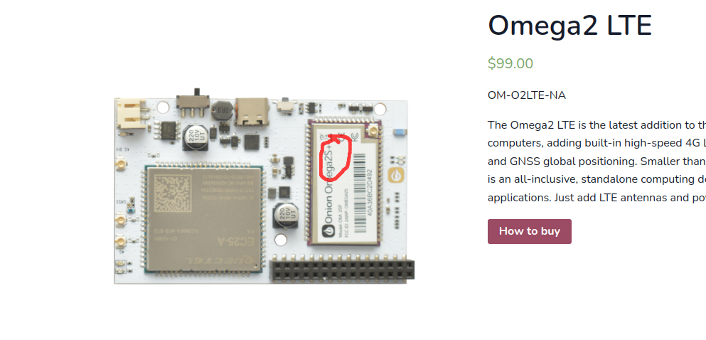
I just checked Omega LTE, and it is using Omega2S+.
Thus, you should use Omega2+ (Omgea2p) image, instead of Omega2 (without +/p).
With Omega2 image force upgrading, it won't boot.
