Yep, agree, looks like a major bug, leading to a kernel panic or something similar.
If you want to check it further (and have no access to the console), make the syslog (or whatever is used) to log kernel logs and perhaps other data to some non-volatile place.
Alternatively, just stream the log to the ssh terminal (tail -f logfile) and maybe you will see some kernel messages before it crashes.
Sorry, I can not be more specific, I don't have any Omega up and running at this moment and I am not sure how the syslog is configured on the Omegas.
Posts made by Marcin Debowski
-
RE: omega2+ shutdown every time I turn my mobile AP onposted in Omega Talk
-
RE: New Omega 2 No Wifi Nothing happening...posted in Omega Talk
@Alex-Hill said in New Omega 2 No Wifi Nothing happening...:
@Marcin-Debowski
Yes, when I first turned it on it went straight to solid Amber light.It's definitely not a good sign. It looks it simply doesn't boot. Serial connection would help to diagnose on what stage the booting process stops. To connect via serial using the UART ports of Omega you would need an external converter like this one:
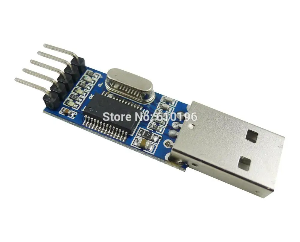
I don't know, whether this is correct for the Omegas, but for the machines like Raspberry Pi, Orange Pi and few other (admittedly relying on SD cards), going straight to solid typically means having problems at the very early booting stage, basically the boot loader not being able to load anything (a kernel) from the storage.
-
RE: New Omega 2 No Wifi Nothing happening...posted in Omega Talk
@Alex-Hill said in New Omega 2 No Wifi Nothing happening...:
I noticed that my Amber light never blinked. It turned solid straight away.
You mean right from switching it on?
Hey all, Received my omega 2 in the post yesterday. Just plugged it in today (Micro USB) I'm using windows 10. I can't see the wifi for the Omega 2.
It takes sometimes a few good minutes for the wifi name to appear on the list.
-
RE: omega2+ shutdown every time I turn my mobile AP onposted in Omega Talk
@sunny-lau said in omega2+ shutdown every time I turn my mobile AP on:
I am currently facing some wifi connection problem so I use different WIFI AP to test.
I found that whenever I turn on my iphone AP and scan wifi with omega2+, it will hang and shutdown(SSH disconnect and LED turns off).
My iphone AP name has special letter (actually a chinese word).
Will it reboot by itself or just "shutdown" and stay disconnected?
-
RE: Getting Real Time from wifi to use in sketchesposted in Omega Talk
@Tyler-Brown said in Getting Real Time from wifi to use in sketches:
Since the omega2+ is wifi, how do I call for the date and time to use in sketches?
In a more simple way of asking, I would like something to turn on at a specific time of day and run for a specific amount of time,
an example, turn relay on Monday at 0600 and then turn relay off at 0605, 5 minutes later.
So, how do I use omega that is connected to the wifi get date and time to apply it to my needs?If I get the above right, a very basic shell script combined with the standard cron functionality is all what you may need.
# below whatever you use to turn the relays on - this is I guess what you call a sketch
my_favorite_relay_script on

# wait for some time (below for 5 min)
sleep 300

# below whatever you use to turn the relays off
my_favorite_relay_script off
Now you define your schedule with the crontab, and this is what you may want to read about it:
https://docs.onion.io/omega2-docs/running-a-command-on-a-schedule.htmlBelow, a crontab file that will execute the command every Monday at 6:00:
0 6 * * 1 /bin/sh /fulpath_to_the script_aboveNote that if you need to switch it on and later off at specific times, you don't need any extra script and you can do it like this:
0 6 * * 1 /fulpath/my_favorite_relay_script on 5 6 * * 1 /fulpath/my_favorite_relay_script off -
RE: Power consumption scenarios of an Omega2+ like boardposted in Omega Talk
@ccs-hello said in Power consumption scenarios of an Omega2+ like board:
@Marcin-Debowski
Place the 470uF cap on DC-DC inverter's output side. Basically, make it more "beefy" in supplying juice.
Hookup your ammeter the way you did it (except this time, on 3.3v side.)It won't boot. The meter adds 1m of wires. I have to prepare first some short solid leads for it.
-
RE: Power consumption scenarios of an Omega2+ like boardposted in Omega Talk
@Ken-Conrad said in Power consumption scenarios of an Omega2+ like board:
@Marcin-Debowski Yes baseline at 3.3V. I use a common bench power supply that has a variable volts output and displays the current drawn, in amps. I believe you have a similar power supply? I have my supply set to 3.3- 3.4V and the amp meter nicely displays the current required at that particular moment of the Omega boot, etc. Not a graph providing setup, but useful and accurate.
Yes, I have it too and I noticed the difference of ca 10% what I contributed to the wires.
I just reread this thread. It is about various problems users had powering their Omegas, including your posts about tests with small Chinese made power supply boards. You mentioned powering an Omega with 5 volts. By accident I did that once with a bare Omega for an hour or more. It ran fine, but got quite hot. After that it always required at least 3.4v to boot completely and now it draws more current ... I believe the 5 volts changed or degraded something in that Omega.
I am pretty sure I didn't power it with 5V but I will cross-check the load with the Omegas2plus I have.
What confuses me is your statement "recalculated from 7.0V to 3.3V". What did you do here? Did you calculate the amps at 3.3V by Ohm' Law for a constant load: A = 7/3.3 x (current measured at 7v) ?
To check your setup you could run this test - in place of the Omega wire a known resistive load, say 80 ohm 1/4 watt resistor or 16-20 ohm 1 watt resistor. Use your graphing to measure the current. Checking with Ohm's law, does the graph make sense?
I think the load depends on the voltage used but within some reasonably narrow range within the DC-DC converter spec, I would expect it to roughly follow the law. In other words, under such condition the load may be considered constant.
I will run some further tests to verify the meter and the setup. I will try to shorten all the lead wires and still place the meter right in frotn of the Omega. The idea with the fixed resistor is a good one too.
-
RE: Power consumption scenarios of an Omega2+ like boardposted in Omega Talk
@ccs-hello said in Power consumption scenarios of an Omega2+ like board:
Place the ammeter on the output side of the DC-DC inverter.
The solution is to put a 470uF 6.3V eletrolytic capacitor near the output sied of DC-DC inverter.To do this right I would need to place the capacitor between the ammeter and Omega. I expected this would "flatten" the characteristics (make a sort of running average) and I wanted to see the spikes of the current if any. What I mean, I expected the recorded current to be in this case strongly dependent on the charging / discharging characteristic of the capacitor and only indirectly on the Omegas short-time load demand - is this assumption correct?
-
RE: Power consumption scenarios of an Omega2+ like boardposted in Omega Talk
@Ken-Conrad, was your baseline for 3.3V? If it was for 5V this would be not that far off (possibly) taking into account the converter under the load.
In my other post on the cheap converters for 5V Vin the idle (stable) Omega2 current was 170-190mA.I tried to put the meter directly before the Omega but it didn't boot. The lead wires look solid but it is still the Chinese-who-knows-what-inside stuff.
-
RE: Air quality monitoring stationposted in Projects
I am going to use the DHT11/DHT22 sensors for temperature and humidity readings. I found one thread within this forum describing how to do it, but the solution presented there is based on a python script executing the cpp compiled binary code. As far as I can see there are some python libraries to read set GPIO so I wonder why this has to be the described way.
My understanding how it works: the sensor is triggered by setting a high level pulse on the GPIO pin. The sensor responds to this pulse returning a wave of pulses with 2 different, fixed durations corresponding to 0 and 1. The task is to decode the pulses by analyzing their width (duration) and assemble them into bytes. This obviously requires sampling the GPIO state into some sort of array. It seems the sampling rate should be with the resolution ~20us (or 50kHz). Is this sort of resolution achievable by the said python module?:
https://docs.onion.io/omega2-docs/gpio-python-module.html -
RE: Power consumption scenarios of an Omega2+ like boardposted in Omega Talk
György's post reminded me that I had a nice tool (VA18B) bought ca 7y ago. Dusted it off a bit.
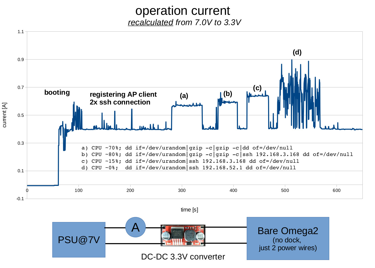
Remarks:
- I coudn't make the Omega to boot when the meter was inserted after the DC-DC converter. Also, it didn't boot when the Vout of PSU was set to 5V.
- The 192.168.52.1 is the WLAN the Omega registers to itself. The reception in the place I ran the tests is poor so I am not sure if this extra power need is because of going over two wlans or because of the poor reception (seems the first one).
- the sampling rate of the multimeter seems to vary between 1 and 5Hz so the peaks (spikes) should be considered as "at least".
- the DC-DC converter draws unloaded ca 7mA
If anybody is interested in any specific test based on the above setup, please let me know. I have Omega2, Omega2plus and the mini-dock.
-
RE: Help omega2 not respondingposted in Omega Talk
@Chris-Stratton
Ooops. I only have the mini dock so I assumed all the other (bigger) have the converter too. Sorry for that and thanks for correcting me. -
RE: Help omega2 not respondingposted in Omega Talk
Edited: my bad, the OP's dock has no converter. Please ignore the text below.
As you seem to use ms windows,
- download and install putty
- boot your Omega using the dock station powering it through the usb cable connected to the laptop
- follow these steps:
https://software.intel.com/en-us/setting-up-serial-terminal-on-system-with-windows
Note: the usb com port of omega should have the UART word within the device description (uart serial ....cp210x? or similar) - press Omega reset button, watch the terminal window and paste here its content
-
Air quality monitoring stationposted in Projects
SBCs are natural platforms for all kind of monitoring stations. With the extra small form factor of the Omegas (not to mention their cuteness) I am planning to make one using them. It may take me some time to wrap all the details up in some final form so I am creating this thread to report initial steps in case somebody is tempted too.
I intend to have at least:
- particulate,
- humidity,
- and temperature
sensors
For the No 1, I eventually would like to use the Plantower PMS5003 sensor, but I have some problems to get it working (non Omega specific) so just to test the connectivity I used Nova SDS021 sensor:


which I am more familiar with.
Nova SDS021 DatasheetThe connector layout:

Note that the sensor requires 5V power supply.
I hooked up the R and T lines of the sensor directly to the UART1 serial 46 and 45 Omega pins, respectively.

The UART1 is represented by the /dev/ttyS1 device.To test the setup I used (further simplified) a python scrip found here: http://www.instructables.com/id/Using-Pm25-Sensor-With-Raspberry-Pi/
import serial
import time

def hexShow(argv):
   result = ''
   hLen = len(argv)
   for i in xrange(hLen):
       hvol = ord(argv[i])
       hhex = '%02x'%hvol
       result += hhex+' '

t = serial.Serial('/dev/ttyS1',9600)
while True:
   t.flushInput()
   time.sleep(1.5)
   retstr = t.read(10)
   hexShow(retstr)
   if len(retstr)==10:
       if(retstr[0]==b"\xaa" and retstr[1]==b'\xc0'):
           checksum=0
           for i in range(6):
               checksum=checksum+ord(retstr[2+i])
           if checksum%256 == ord(retstr[8]):
               pm25=ord(retstr[2])+ord(retstr[3])*256
               pm10=ord(retstr[4])+ord(retstr[5])*256
               print "pm2.5:%.1f pm10 %.1f"%(pm25/10.0,pm10/10.0)
The code requires python-serial (and python-light) to be installed.
An example of the outputpm2.5:14.9 pm10 15.7 pm2.5:15.0 pm10 15.8 pm2.5:15.1 pm10 15.9 pm2.5:15.1 pm10 15.9 pm2.5:15.2 pm10 16.0 pm2.5:15.2 pm10 16.0 pm2.5:15.3 pm10 16.1 pm2.5:15.4 pm10 16.2 pm2.5:238.6 pm10 578.7 <- lit on fire a piece of paper and blew the smoke towards the sensor pm2.5:373.1 pm10 960.4 pm2.5:613.1 pm10 1375.7 pm2.5:719.8 pm10 1532.1 pm2.5:892.8 pm10 1734.9 pm2.5:891.4 pm10 1670.3 pm2.5:999.9 pm10 1999.9 pm2.5:999.9 pm10 1984.0 pm2.5:999.9 pm10 1752.8 pm2.5:999.9 pm10 1640.8 pm2.5:755.6 pm10 793.4 pm2.5:709.9 pm10 745.4 pm2.5:602.6 pm10 632.8 pm2.5:531.7 pm10 558.3 pm2.5:429.2 pm10 450.7 pm2.5:436.3 pm10 458.2 pm2.5:474.7 pm10 505.9 pm2.5:499.1 pm10 535.4 pm2.5:439.2 pm10 461.2 pm2.5:421.5 pm10 442.6 pm2.5:388.1 pm10 407.6 pm2.5:378.9 pm10 397.9 pm2.5:258.6 pm10 271.6 pm2.5:175.7 pm10 184.5 pm2.5:88.4 pm10 92.9 pm2.5:84.0 pm10 88.3 pm2.5:75.9 pm10 79.7 pm2.5:71.8 pm10 75.4 pm2.5:65.6 pm10 68.9So as it can be seen the whole installation and wiring are very simple and straightforward.
The mentioned sensors are priced (Aliexpress) between USD15 and 30. -
RE: Omega 2 - Ethernet without Ether dock?posted in Omega Talk
Thanks Luz.
I checked the Hanrun HR911105A module in the meantime and it works without any issues. Direct connection (T to T and R to R, not a cross-over).
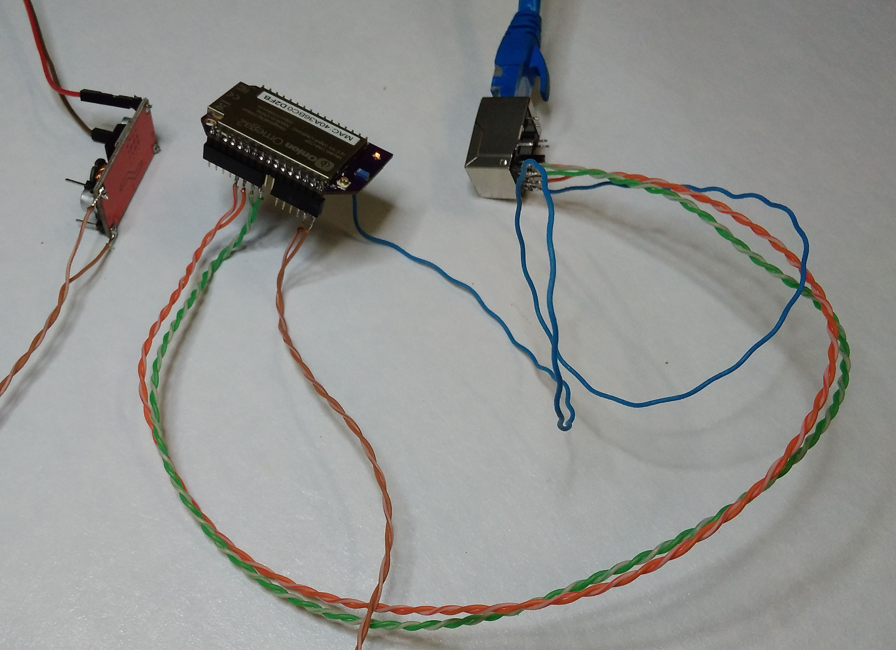 .
.After all the wiring is done, for a quick test, the network configuration file needs to be edited as per this document:
https://docs.onion.io/omega2-docs/ethernet-bridge.html#step-2-enable-the-omegas-ethernet-connection
and if all was done correctly, the ethernet port should start acting as a WAN if (and Omega as a hot-spot). -
RE: Omega 2 - Ethernet without Ether dock?posted in Omega Talk
@Thomas-Mason
@ccs-hello said in Omega 2 - Ethernet without Ether dock?:Tx C.T. and Rx C.T. tied together then go thru a cap to Ground.
There is no need to connect to Omega 2+ side.Note that EasyJack is not a common part to get in a regular electronic store.
Not that regular but I think pretty available. For example, HR911105A. I got some from Ebay, ca USD4.5 per 5pcs:

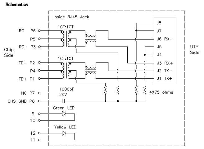
Didn't have time yet to check them out.
I found much more difficult to find a human solderable solution for the USB protection circuit and ended up purchasing individual diodes.
-
RE: Access point not foundposted in Omega Talk
Sorry for coming back late, just waited for parts to arrive and a bit of free time to play with them
As mentioned, I used exactly the same bench-top PSU as shown above and a bare Omega2.
-
Wires (direct connection to the Omega)
The PSU at 3.3V/1A
a) 2m long AGW18 wire, multistrand, diameter ca 2.3mm - no problem to boot and work stable
b) 4m long, multistrand, dia 0.8-0.9mm - it draws 45mA but even the power LED stays off. -
Cheapo DC-DC boards purchased from Ebay
I got 3 of them, the two smaller are single voltage ->3.3V, the bigger one converts to 5V and 3.3V
All the tests below are done with the 4m long thin wire.
Overview:
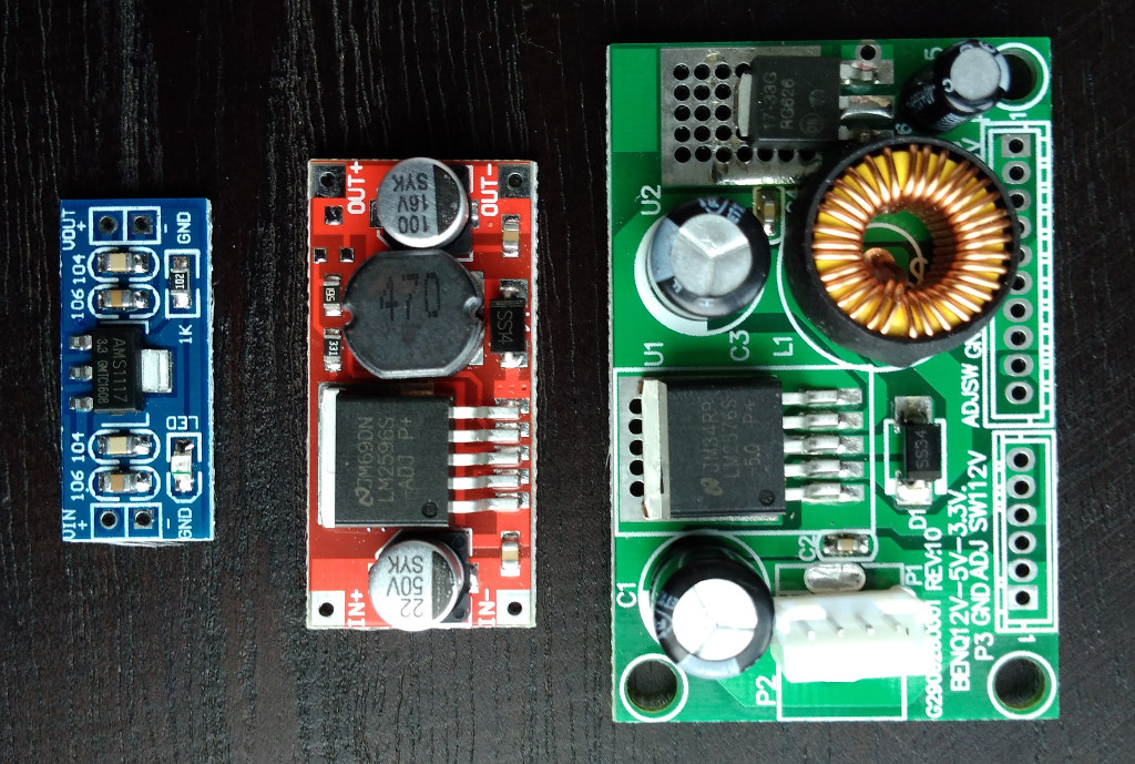
Tiny: ~USD1; *As described by the seller: Input: DC 4.5V--7V (Input Voltage must be Greater than the Output voltage high above 1V.)
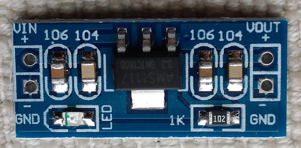
out 3.3V
Boots but keeps restarting.
With a 870 uF at the output:
in 5V: boot time 170-190mA, stable: 170-180mAMid-sized: ~USD1.8; As described by the seller: 10W DC Buck Step Down Regulator Voltage Power Converter Module 3.6v~40v 2A 3.3v
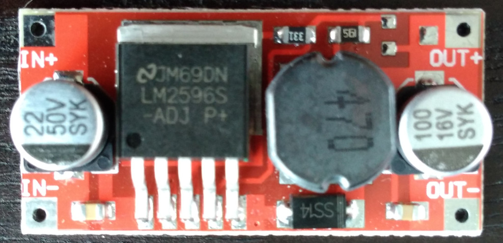 out 3.4V
in 5V: boot time 140-230mA, stable: 165-185mA
in 12V: boot time 40-75mA, stable: 70-75mAThe big one (5V and 3.3V): ~USD2.75; As described by the seller: DC-DC 12V To 5V 3.3V Step-down Power Supply Module, max 3A.
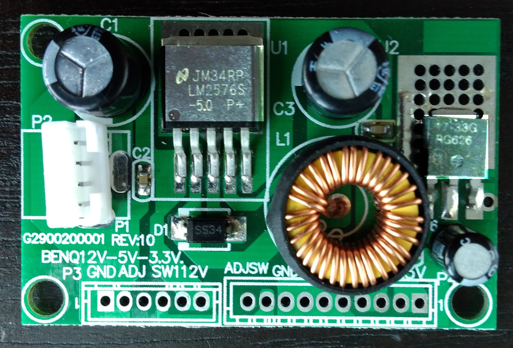
out 3.3V
in 5V: doesn't boot
in 12V: boot time 70-130mA, stable: 100-110mAAnd of course, the advice to add some large capacitors at the output was hitting the nail on the head. The 1117 and its clones make the Omega to boot and work stable with no problems including this 4m poor quality wires. I checked some electrolitic and tantalum capacitors in the range of 800-1000uF.
One more piece of info, I arbitrary limited the current booting with the input of 3.3V, the 2m long 2.3mm conductor and 200-300mA is no go, but 500mA already boots and stays stable (at least for the bare Omega2 used).
Question: is the Vin of 3.4V for the Omages a major concern? I liked the middle-sized converter but this is also the only with the Vout out of range (for both 5V and 12V Vin).
-
-
RE: Access point not foundposted in Omega Talk
Oh, sorry, I searched some threads but I used the 1117 step down chip as the keywords. I believe I've seen one or two remarks on the cable length but I am a chemist so some things for me are just not that common sense. I assumed the lead wires from the 3.3V PS are critical - these I kept short, but I would never guess also what leads to the 3.3V converter is that critical.
I tried capacitors up to 33uF on the Omega2 side but never went beyond that. Thanks for the info, I will order some.