gps receiver not locking
-
I logged a ticket but so far it is sitting at processing with no reply from anyone.
The active antenna arrived and at present with it sitting on the desk in the office (well away from any windows) i am seeing between 9 and 12 satellites and it has a fix.
Will try it on the omega shortly.
-
Hmm
Well same problem here, on the Omega2+ I am not able to get a gps fix at all doesnt matter where i put the gps expansion... Same problem with the program under windows.
So also wondering if I might have a faulty gps expansion as well... Had to go through hoops and hurdles to get the Omega2+ going as, bad soldering which had to be removed but now that is at least working.
regards,
Leo
-
I think it may be an antenna issue. The external antenna has worked perfectly now and gives a good solid fix
-
@Ian-Marchant Yes agreed it might very well be a faulty antenna or just the antenna being quite small. I don't have an external antenna lying around unfortunately but will try experiment with one, once I find one
 Ow well experimentation can be fun !
Leo
-
had re reply to my ticket this morning which may help a little.
"There might be a design problem on GPS. We are sorry for that. It is not defective issue. There is a capacitor add wrongly on GPS. But due to the short of resources we are unable to fix that before campaign. The problem is harder than we expected. We will try our best to solve it thanks to your support. If there is new GPS version. We will let backers know as soon as possible. There is a way to solve that. Start from Antenna connector to the USB header, the second yellow component is the wrong capacitor. Right after the white inductor. Try dis-solder the capacitor, and you can get GPS fixed."
-
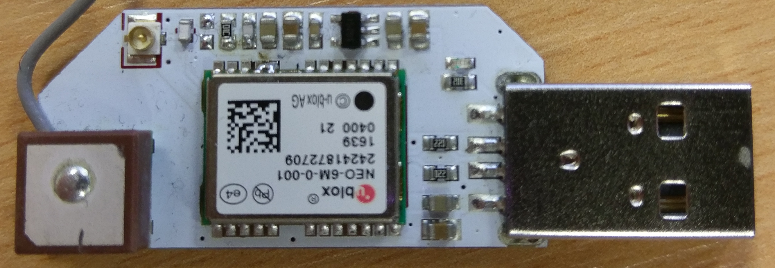
From this photo however, I am not 100% sure which part i am supposed to use?

-
@Ian-Marchant That's interesting I think I know which component is meant but desoldering an SMD type capacitor is not something I would love to do without the proper tools ie soldering equipment... If they promise me on my ticket, which I opened for this isse(no updates what so ever till now...), to send me a replacement I might just go for it. If I do I will let you know the results.
greetz,
Leo
-
@Ian-Marchant Maybe someone from @administrators can put a picture with a circle around the right capacitor on here, I also asked this on my running ticket.
your right the description in that message is somewhat unclear

regards,
Leo
-
I also have the same issue being unable to lock onto a satellite both indoors and outdoors.
-
From the ticket reply I suspect there are lots of users with GPS devices that need to be returned to sender.
Could just be a small bad batch but I'm guessing at a large batch as they don't make these in one's and two's.
-
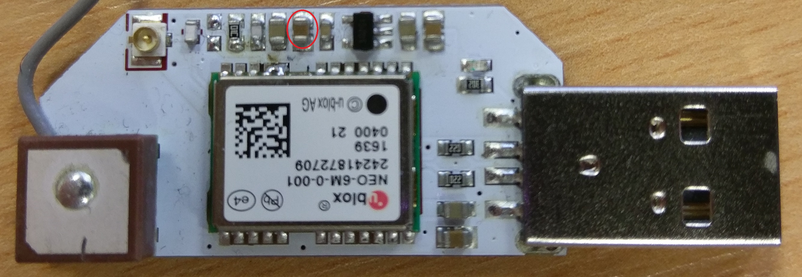
Personally after reading the description several times i believe its the red encirceld capacitor which needs to be desoldered.. might just give it a go regardless since the expansion is useless currently anyway...
Regards,
Leo

-
@Leo-de-Blaauw I would concur but the ticket is far from clear.
I'm gobsmacked that a supplier even suggests such a fix without first acknowledging they are financially liable for a replacement if the end user is unable to do the suppliers remedial work for them. This includes messing around with the wrong resistor because their instructions are ambiguous.
-
@Costas-Costas true, but in their defence i had a soldering bridge on my omega2+ they have promised to send me a replacement on my ticket for that issue. So went ahead and fixed it and it is working fine now. Replacement not yet here though..
-
I have the same issue. Anybody tried to unsolder the cap yet?
-
I am waiting for a definite response on my support ticket. Will post update when I get one.
-
@Leo-de-Blaauw said in gps receiver not locking:
Personally after reading the description several times i believe its the red encirceld capacitor which needs to be desoldered.. might just give it a go regardless since the expansion is useless currently anyway...
No. The description you post appears to be about the capacitor which is already absent from your board.
Start from Antenna connector to the USB header, the second yellow component is the wrong capacitor.
That describes something that could have been on the pair of silvery solder-covered pads 2nd in from the antenna connector. Effectively, the proposed rework or change has already been implemented on the board you picture.
The capacitor you have circled is a much larger one, probably part of a power supply circuit. Removing it is not a good idea.
However, it's not clear if just having the rework proposed is going to be enough, question would be if the resistor to the right of that is part of the bias supply to the antenna pin, and the removed capacitor was erroneously in parallel with it, or if the capacitor was where the resistor was supposed to be. Some time finding the traces under the soldermask and drawing out the circuit to compare with other published ublox ones could probably solve it, but frustration in being sent non-working hardware is understandable.
FYI the apparent solder bridge between two ublox pins reflects an apparently intentional connection on at least some schematics that have been published. It's fairly common for a bridge to form between two pads that are already electrically connected, though of course it still catches the eye and is a suspect to investigate when something doesn't work.
-
@Ian-Marchant said in gps receiver not locking:
From this photo however, I am not 100% sure which part i am supposed to use?

If that is a picture of your receiver then it's time for an RMA following the comments from Chris Stratton. Or did Onion send you the photo?
-
Hi,
That is a picture of my board as it arrived from Onion. I have not made any modification at all.
The only thing I have done to it is to disconnect the antenna and connect an external active antenna. Once the external antenna is connected I get a solid fix with no issues. With the internal antenna... nothing.
Cheers.
-
So you are unable to carry out the remedial work requested by Onion as the rogue capacitor doesn't appear to be there. I would send it back as faulty.
-
Working with an external antenna would not be inconsistent with my suspicions, but those are formed from only a few minutes looking at your picture and a schematic of a different board.
Anyway, it looks like the suggested rework is already applied, so no use for your soldering iron right now. If you do want to poke at it with tools, you could consider with the system unpowered measuring the resistance between the bridged pair of pins on the module and each side of the white ceramic chip inductor beside the antenna. That is not guaranteeed to be 100% safe for all circuit but is usually tolerated, and could help show if there's an issue with the antenna bias supply.
I have to stress though that this is all guesses.