How to control WS281x RGB LED strip?
-
You can install a kernel module for that from @luz repository here: https://github.com/plan44/plan44-feed/tree/master/p44-ledchain. There are people who have already made projects with that (https://www.youtube.com/channel/UC88qf_c6e8lCvcAbQP9UtSA, https://onion.io/2bt-neopixels-galore/, https://community.onion.io/topic/2164/omega2-arduino-dock-2-neopixels/5).
-
@luz said in How to control WS281x RGB LED strip?:
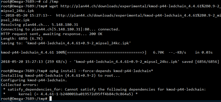
opkg install --force-depends kmod-p44-ledchain*
Error.

-
@luz
In first time when do this:
insmod /lib/modules/4.4.61/p44-ledchain.ko ledchain0=0,10,2
omega2-ctrl gpiomux set pwm0 pwm
echo -en '\xFF\xFF\xFF\xFF\x00\x00\x00\xFF\x00\x00\x00\xFF' >/dev/ledchain0
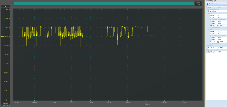
Oscilloscope show signal.
After reboot - signal is disabled.
Repeat command - doesnot give effect.
I do this for pwm1:
insmod /lib/modules/4.4.61/p44-ledchain.ko ledchain1=0,10,2
omega2-ctrl gpiomux set pwm1 pwm
echo -en '\xFF\xFF\xFF\xFF\x00\x00\x00\xFF\x00\x00\x00\xFF' >/dev/ledchain1
Oscilloscope show signal on pwm1.
After reboot I cant get signal on pwm0 or pwm1
-
@Alexandr-Didenko said in How to control WS281x RGB LED strip?:
@luz said in How to control WS281x RGB LED strip?:
opkg install --force-depends kmod-p44-ledchain*
Error.
Yeah, that's a bit confusing.
opkgdisplays the error (which is more of a warning in this case, meaning that installation would have failed if the--force-dependsoption was not set) altough the operation has succeeded.So everything's fine so far

Now for the signal disappearing after reboot:
omega2-ctrlsettings are not permanent, and activation of p44-ledchain viainsmodisn't, either (only installation via opkg is!).To get the ledchain ready automatically after boot, just put the
omega2-ctrlandinsmodlines into a startup script./etc/rc.localis a good place for that, unless you have your own startup script for your application, where you can put such initialisation code as well.
-
@luz!
Thanx for all!
Signal on oscilloscope - i see.
Connect strip.
write string:
echo -en '\xFF\x00\x00\xFF\x00\x00' >/dev/ledchain0
And repeat this about 3 second.
And strip behaves strangely.
First two diodes some times is red.
But mostly they are not red.
And mostly first 3-4 LEDs are lighting too. And all colors of all 2-4 LEDs are random.insmod /lib/modules/4.4.61/p44-ledchain.ko ledchain0=0,2,2
Try ledtype 0,2,*(0-4).
Try inverted 1,2,2.String
echo -en '\x00\x00\x00\x00\x00\x00' >/dev/ledchain0
switching off 2-4 LEDs not the first time. And this string switch off 3 and 4 LEDs too. sometimes
Strip I connect through logic level converter 3.3V<->5V. He is worked with arduino and ESP8266.
And try connect directly to omega2.Strip still behaves strangely.
1.

2.

3.


-
@Alexandr-Didenko
It definitely sounds like a hardware problem.This is exactly what happens when the logic high output level of the 3.3V Omega2 is just at the minimum level for 5V WS2813 to be recognized.
For testing, it might help to lower the 5V supply a tiny bit (4.9V instead of 5V, easy to try if you have a lab power supply), because this also lowers the logic high threshold of the WS2813 chips a bit.
A logic level converter is certainly the way to go to make that reliable - but the type you chose is most certainly way too slow for the WS2813 signal. These bi-directional thingies are good for serial speeds (many offers do not properly spec, but those that do say max 28800bd). The WS281x signal is in the 1mbps range, however.
For that you want to use a unidirectional level shifter, such as the 74AHCT125 (or its single-gate version, 74AHCT1G125). I used that one successfully for my "pixelboard", see schematics, with 200 WS2813.
-
74AHCT1G125 litle improved situation.
But LEDs all the same, often have chaotically color.
Tried strip WS2813 in another packet.
Tried another power supply.


-
@Alexandr-Didenko I have no real idea why it does not work reliably in your case (it does in mine).
To make sure the timing works ok, you can check the stats of the ledchain driver:
root@pixelboard:~# cat /dev/ledchain1
Ready
Last update: 0 repeats, last timeout=0 nS, max irq=9484 nS
Totals: updates=99756463, overruns=0, retries=3745, errors=4, irqs=2079220056
If you have a high
errorsnumber, then something (most probably another driver) is blocking IRQs too long, causing incomplete LED chain updates. Getting someretriesis normal. In my example, the number seems high (3745) but that's over a uptime of 46 days, with 99 million full chain updates, so the retry rate is 0.0038%However, I don't see how even lots of retries/errors would cause anything else than the chain not fully updating. But not completely chaotic colors.
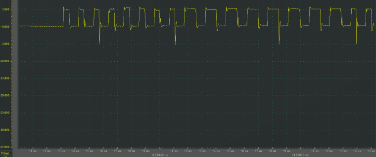
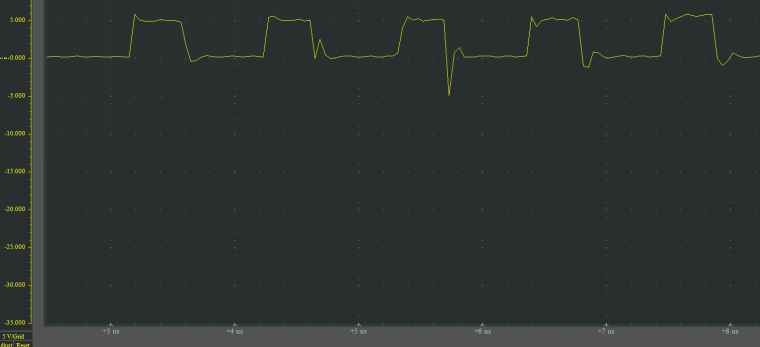
So I still suspect something in the hardware. The really sharp downwards spikes seen on your scope screenshots look suspicious. I can't really make sense of these, occuring only every 5th falling edge.
How do you power the LED strip? Direct fat wires from the LED strip to the PSU, for +5V and GND?
-
@luz thanx for support.
New video: youtube.com/watch?v=5GpZlGmnKGs.
I send string many times:
echo -en '\x10\x00\x00\x10\x00\x00\x10\x00\x00' >/dev/ledchain0
And here is chaotic colors.
But!
Sometimes led strip work properly.cat /dev/ledchain0: Ready Last update: 0 repeats, last timeout=0 nS, max irq=10575 nS Totals: updates=87, overruns=0, retries=0, errors=0, irqs=286
Strip power:
From laboratory power supply +5V to +5V strip and to AMS1117_3.3. GND to Omega and to GND strip.
Data wire frompwm0 (G18)topin 274AHCT1G125.
74AHCT1G125:1 and 3 pintoGND,5 pinto+5V,4 pinto strip WS2813pin DI.
Three LEDS don't need in fat wires.
-
@luz
in your schematicsLEDCHAIN_DATA_3Vconnect toG46/UA_RX1.
I connecting topwm0 (G18).
Does it matter?
-
@luz Thanx! WS2813 and WS2818 work!
https://www.youtube.com/watch?v=rqpyM6vhPLA
-
@Alexandr-Didenko nice device! I assume your I/O are i2c or SPI based? If so, your hardware could run as a digitalSTROM gateway, just by running my vdcd on it. Any plans to open source your device? Or produce and sell it?
BTW: how did you get the WS281x to work, finally?
-
@Alexandr-Didenko nice device! I assume your I/O are i2c or SPI based? If so, your hardware could run as a digitalSTROM gateway, just by running my vdcd on it. Any plans to open source your device? Or produce and sell it?
-
@luz I/O - MCP23017 - i2c. My plans - to sell it.
I don't know what I do, that WS281x to work
Honestly!
It suddenly began to work.
I thing that oscilloscope give interference.
-
@Alexandr-Didenko said in How to control WS281x RGB LED strip?:
@luz I/O - MCP23017 - i2c. My plans - to sell it.
Let me know when it becomes available

I don't know what I do, that WS281x to work

Honestly!
It suddenly began to work.
I think that oscilloscope give interference.
Could be, depending on the probe. Anyway, I'm glad you have it working now!
-
@luz!!!
In your schematics I seev-neton the Omega.
What is this?
And how workETHLED_AMPEN (PWM/G18)?
I connect to G18 (PMW0)LEDCHAIN_DATA_3V.
Why you connectLEDCHAIN_DATA_3VtoG46/UA_RX1?
G45andG46(UART1) doesn't havePWM
-
Hi @Alexandr-Didenko !!!!!

-
V-NETis not connected on the Omega2. It is here for compatibility with the Omega1 which had different ethernet PHY logic that needed a bias voltage on the center taps of the ethernet transformers. I started with Pixelboard before the Omega2 came out... -
ETHLED_AMPENis just a GPIO I'm using for switching the audio on and off in the Pixelboard as it is now, but I had variants w/o audio so I also connected it to the ethernet jack's LED. The idea was to have it show ethernet activity using theledtrig-netdevLED kernel module. I tried once briefly, but it didn't work right away. -
PWM on
G46: the pin mux in the MT7688 has several options of exposing the PWM outputs, not just GPIO 18 and 19. A while back I posted a annotated pinout of the Omega2 (and 2S) with all possible pin functions labelled - that helped me a lot to design Omega2(S) circuits.
You can switch theuart1group topwm01withomega2-ctrlto get PWM1 onG46.
-
-
@luz said in How to control WS281x RGB LED strip?:
You can switch the uart1 group to pwm01 with omega2-ctrl to get PWM1 on G46.
How? On the Omega2S+
omega2-ctrl gpiomux getsay that uart1 doesn't have pwm options.root@Omega-6E01:~# omega2-ctrl gpiomux get Group i2c - [i2c] gpio Group uart0 - [uart] gpio Group uart1 - [uart] gpio Group uart2 - [uart] gpio pwm Group pwm0 - [pwm] gpio Group pwm1 - pwm [gpio] Group refclk - refclk [gpio] Group spi_s - spi_s [gpio] Group spi_cs1 - [spi_cs1] gpio refclk Group i2s - i2s [gpio] pcm Group ephy - [ephy] gpio Group wled - wled [gpio]
-
Hi @Alexandr-Didenko, are you sure you have the latest omega2-ctrl? Your screendump looks like a version prior to April 2017, when @Lazar-Demin merged my patch fixing exactly those missing modes for the uart groups.
Judging from the makefile in the Onion OpenWrt feed, any build of omega2-ctrl done since April 2017 would have pulled from the omega2-ctrl
HEADand thus included the patch.However, it seems that @onion might have forgotten to bump the package version back then, and if they never rebuilt the FW from scratch since, it might be that even recent FW builds still contain the pre-April 2017 version

Maybe just try to force-update it via opkg:
opkg update
opkg --force-reinstall omega2-ctrl
The April 2017 version will show:
root@Omega-WXYZ:~# omega2-ctrl gpiomux get
Group i2c - [i2c] gpio
Group uart0 - [uart] gpio
Group uart1 - uart [gpio] pwm01
Group uart2 - uart [gpio] pwm23
Group pwm0 - pwm [gpio]
Group pwm1 - pwm [gpio]
Group refclk - refclk [gpio]
Group spi_s - spi_s [gpio] pwm01_uart2
Group spi_cs1 - [spi_cs1] gpio refclk
Group i2s - i2s [gpio] pcm
Group ephy - [ephy] gpio
Group wled - wled [gpio]
-
@luz Good catch! We, in fact, did not up the version number of
omega2-ctrl
I've upped it now and a v0.2 will be available when we release the next fw build