Omega2S+ sys_led pin
-
Does anyone know which pin is sys_led on Omega2S? I can't find it in the docs.
-
@crispyoz GPIO 43 - it's pin 18 according to pin numbering of Omega2S(+) Data Sheet Version 1.6
BTW Onion Omega2 Pro The Amber Status LED section of Official Omega2 Documentation has a typo:
The Omega LED uses GPIO44, and can be programmed to do a number of cool things.
GPIO 44 ie. pin 19 controls only the WLED - the WiFi Status LED
[Edited] on an Omega2 Pro board with the present FWs (up to b232).
-
@György-Farkas I suspected it is Pin 43 based up on the Omega 2 Pro schema but I don't see it in the datasheet.
Already have pin 44 in use.
-
@crispyoz @György-Farkas
For Omega2/2+/2S/2S+ firmware, the system LED is GPIO44. See theWLED_N / GPIO_44pin in the Omega2S datasheet.For the Omega2 Pro and LTE, we changed GPIO44 to be a wifi status LED and moved the system status led to GPIO43. This is only valid for Pro and LTE firmware since this change was made in the DTS files for these two boards.
-
@Lazar-Demin Yes, you are right the Omega's System Status LED pin is not determined by the hardware. I assumed @crispyoz was talking about [Omega2S+ and Omega2 Pro].
And there's a typo in Onion Omega2 Pro The Amber Status LED section of the documentation.")
-
@Lazar-Demin @György-Farkas thanks, I was starting to think I was stupid. This explains some inconsistent outcomes I was experiencing.
-
@Lazar-Demin 5 years later - and I still have a question/problem related to GPIO44
I knew GPIO44 is the system LED in standard firmware, so I changed the DTS for my builds long ago to use the not exposed GPIO35 instead, as I needed GPIO44 for other things, in particular enabling some drivers that must not be active before firmware is fully up. This relies on GPIO44 remaining in reset state (configured as GPIO input), so an external pullup can keep the drivers disabled until my code gets active.
Today, debugging a device, I found that GPIO44 is getting configured as output and set to low actively somehow very early, like ~0.5 seconds after reset.
I use devmem in the earliest point where my code gets active to dump
GPIO_CTRL_1, and it returns0x00001008which means GPIO44 and GPIO35 are set to output.
GPIO35 is expected because my DTS assigns it as system LED, but GPIO44 is not expected.Any idea which part of the code would initialize GPIO44 as output before DTS gets active? Is this hard-coded in the omega2 uboot (which I haven't touched, so it is in factory state)?
I am confused by this because I've been using this type of driver enabling circuitry for a long time, and would think I'd have noticed this behaviour of GPIO44 long time ago...

-
@luz The bootloader can also be used to control state of the GPIO earlier than when he dts is loaded, you may recall the issue with the Omega2Pro where the LED was flapping around during boot. The changes are in lib_mips/board.c of in the onion bootloader code.
I discovered this while investigating this issue
If you don't have the code here are the steps to download the relevant code.
-
Today, debugging a device, I found that GPIO44 is getting configured as output and set to low actively somehow very early, like ~0.5 seconds after reset.
@luz I would agree with @crispyoz's suggestion to take a closer look at the bootloader.
In 0.5 seconds after reset, Linux should be booting up, but it's possible the device is still in the bootloader and the bootloader is making some gpio or gpio muxing changes.
Another thing to look out for:
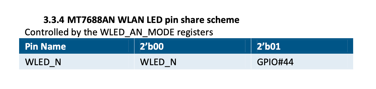
Since the GPIO44 pin is multiplexed with WLED wifi activity LED, it's also possible it gets temporarily flipped to the WLED mode - This is controlled by the GPIO2_MODE register
Let me know how it goes and if you need any pointers!
-
Thanks @crispyoz and @Lazar-Demin for the hints!
I found the lines that makes GPIO44 an output in uboot in
lib_mips/board.c:3012://gpio44 output gpio_ctrl_1 bit3=1 val=RALINK_REG(RT2880_REG_PIODIR+0x04); val|=1<<12; RALINK_REG(RT2880_REG_PIODIR+0x04)=val;(
RT2880_REG_PIODIR+0x04is MT7688's GPIO_CTRL_1 at 0x10000604)Interestingly this was in the initial commit in 2016 by @youlian-troyanov, so GPIO44 being used by uboot seems to be something predating Omega2 related changes and is hard-coded for any
lib_mipsbased setups.As in many cases there will be the WLAN LED connected there, it makes sense also using it for some signalling in early boot stages.
And in fact, this is done in
led_on()andled_off(), curiously using literal hex addresses forGPIO_DSET_1/GPIO_DSET_1, seelib_mips/board.c:3047ff:void led_on( void ) { //gpio44 gpio_dclr_1 644 clear bit12 RALINK_REG(0xb0000644)=1<<12; } void led_off( void ) { //gpio44 gpio_dset_1 634 set bit12 RALINK_REG(0xb0000634)=1<<12; }I would be much more nice to have:
//gpio44 gpio_dclr_1 644 clear bit12
RALINK_REG(RT2880_REG_PIORESET+0x04)=1<<12;
and
//gpio44 gpio_dset_1 634 set bit12
RALINK_REG(RT2880_REG_PIOSET+0x04)=1<<12;
Another curious thing: Why is the address used in uboot 0xb0000000 based (
RALINK_SYSCTL_BASE), while in the datasheet the addresses are 0x10000000 based? Probably because address decoding is 29 bits only, so the I/O block is mirrored at every 0x20000000?Anyway, as GPIO44 is one of the few pins that allow pullups or pulldowns at startup and do not have another special function, I'll probably patch my uboot to leave it alone for my Omega2S devices.
What I still do not understand is how I could not notice GPIO44 flapping around in all the circuits I've done with the assumption it would not

-
@luz said in Omega2S+ sys_led pin:
I would be much more nice to have:
//gpio44 gpio_dclr_1 644 clear bit12
RALINK_REG(RT2880_REG_PIORESET+0x04)=1<<12;Agreed! There's many instances of this type of thing in the omega2-bootloader codebase, among other quirky code.
There were many different contributors and we didn't have coding standards or best practises defined at the time.Our philosophy on this bootloader is currently "if it ain't broke, don't fix it." That said, we do welcome PRs if you're inspired.
Since we're on the topic of bootloaders:
We're also contemplating moving to modern u-boot. The issue there is the default bootloader binary is over 512kB, while the Omega2/2+ device definition only partitions 192kB for the bootloader.
So any devices with the new bootloader would be incompatible with the existing firmware images.
Alternatively, we could add a new variant/SKU that is the same hardware (as the Omega2S+) but runs the new bootloader. This involves logistical challenges.We're open to suggestions on this front. Let us know what works for you, Onion Community!
-
@Lazar-Demin It's clear there were no coding standards, when I first looked at it I was a bit agast, but it's old and open source projects have come a long way since those days, try submitting that to the Apache project.