i2c device not visible by i2cdetect
-
Hi @Andrei-Railean So just to make sure I understand your problem, the Omega has no problem detecting the I2C for OLED, but it's unable to detect your sensor. But an Arduino sketch has no problem detecting your sensor?
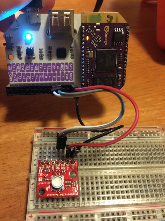
Can you take a picture of your setup with the sensor for us? Let's see if there's any issue we can identify visually.
-
Have the same issue with HTU21D, fully detected by a Rpi but no detection on omega. But on the other hand i have another HUT21D that is detected normally. Since both cases they are assembled in tiny boards i've bought on ebay(they came from china), i suppose that the ones that are not detected may have the pullup resistors for SDA and SCL missing. Didn't loose much time on that but i do believe that omega doesn't have internal pull-ups as the Rpi, so the problema is shown in one side and not on the other.
-
Hey @Boken-Lin i'll wire it up and take a picture or two when I get home.
I don't know much about i2c, but could there be a mismatch in clock frequencies or timings?
I'll try to get my hands on a logic analyser to compare the timings of i2c signals between my arduino and omega.Is there a i2c spec for Omega and/or the expansion board?
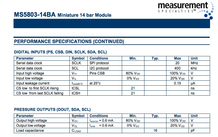
Here's part of the spec from my sensor.

-
Hi @Andrei-Railean, as far as I know I2C should be pretty universal. And it was working at some point with the Omega. So I think the most likely reason is that something is not connected properly.
-
The sockets on the header are quite wide - all my jumper cables feel loose. I suspected that maybe there's no contact. After measuring i did see voltage on the sensor. I can also see that the omega "sees" something on the i2c pins as it responds to i2cdetect instantly. When there's nothing connected, it probes each address and it takes a while. This happened to me before but then it magically fixed itself. Not this time. Maybe loose contacts are causing jitter in the i2c lines.
I'll play around tonight and report back with pics of my set up.
-
@Andrei-Railean Ok. Sounds good!
-
I have a bit of progress, @Boken-Lin. When sensor is connected to 2 or 2.5V on expansion, it comes up in i2cdetect. When connecting to 3.3V - it doesn't.
Power Readings:
- Pin 2.0V => V: 2.113 - Detected - within operating range
- Pin 2.5V => V:2.696 - Detected - within operating range
- Pin 3.3V => V:3.412 - NOT Detected - within operating range - 3.3V is the recommended voltage for sensor
When I try to measure the current by connecting the ammeter in series on the 3.3V line, the sensor gets detected. When I remove the meter, it's not detected.
My conclusion (with my limited electronics understanding) is that it has something to do with the current. Is it possible that it can't get enough? Maybe when I connect the ammeter, it forces more current through the sensor and makes it work.
I observed the same behaviour when connecting to my MacBook's USB port (I believe it's 500mA max) and when using a 2.1A 10W USB power supply. I connected via serial (USB) or ssh. When connecting to serial, I tried powering down the wifi (
wifi down) to see if that has any impact - NONE.I may have accidentally connected it incorrectly before (to 2.5V line) so it was working. Later when I connected it correctly, it stopped.
Conclusion: For now i'll just use the 2.5V line.

-
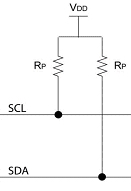
@Andrei-Railean as @Pedro-Baco mentioned, it could be a problem with pull up resistors. Can you try set up your circuit like this

where VDD is 3.3v and Rp is resistor of any value. (preferably 1k~10k).Give it a try and let me know if your omega is able to detect your sensor with this setup.
-
@Andrel Railean
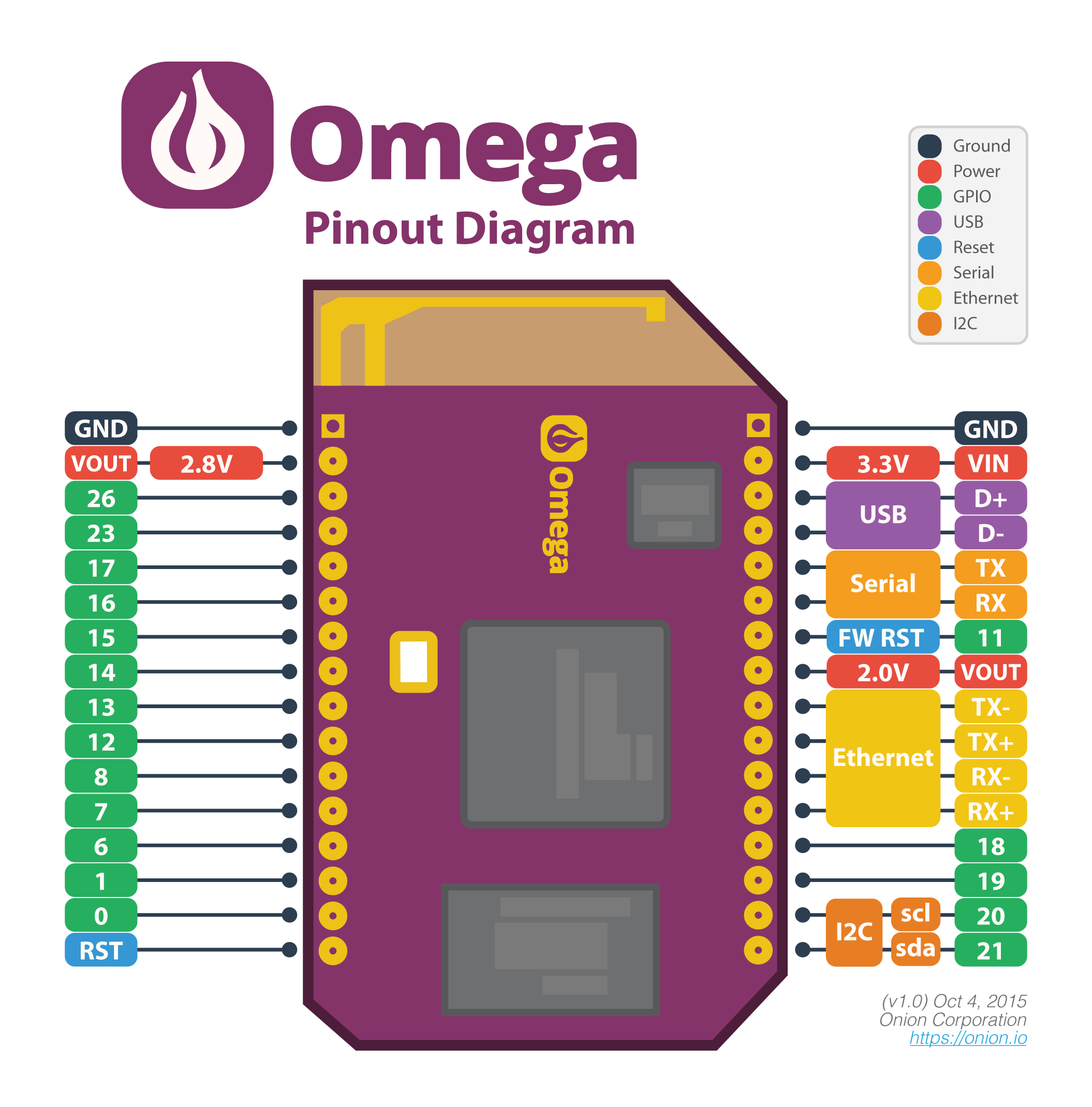
The reason you get no detection when plugged into the 3.3v pin is because the 3.3v pin is an Input for power in. It is not an output. The only power outputs are the 2v and 2.5v pins.
Hope this helps.
-
Not sure why pull-up resistors are not needed for 2 and 2.5v.
There's voltage on the 3.3v line, so I wouldn't call it an input line.
-
This is where the Input idea comes from for the 3.3v line.

-
Though we don't have schematics, my assumption is that the 3.3v is generated on the Expansion Dock (from the USB cable) and is both supplied to the Omega and also to the 3.3v pin on the Expansion Dock
-
@Kit-Bishop That is my understanding aswell, the Omega is already drawing around 200mA of current. So in effect he is trying to put the sensor in parallel with the Omega, power-wise.
If the OP has a breadboard PSU use that for the power otherwise use the Vout shown in the diagram.