Using Omega with LED lightstrips
-
Would you be so kind as to post the type of strip you used would like to duplicate your setup.
-
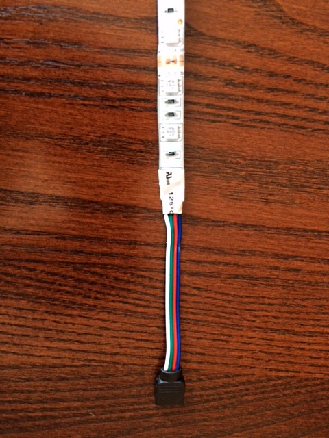
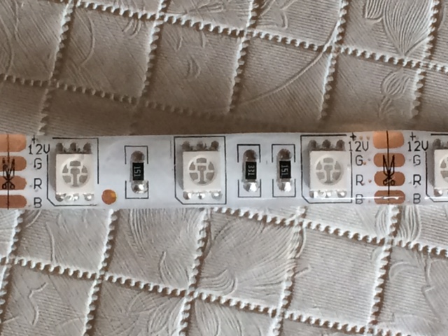
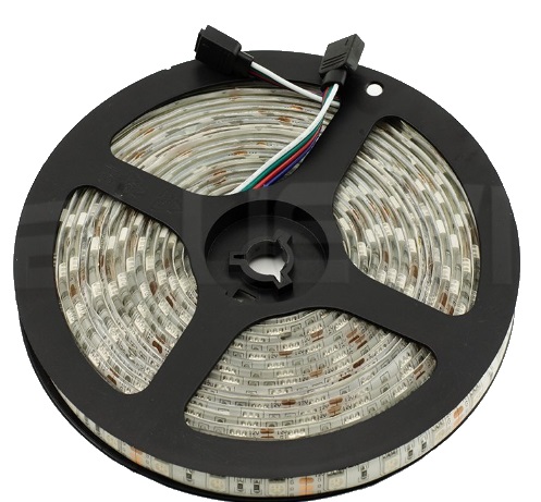
Here are photos of the light strip. The strip itself is 5 meters long, and is usually sold wrapped around a spool:
-
Great job @Jeff-Verive appreciate the pics.
-
I also have a simple Python script (see below, and available at https://gist.github.com/jverive/a24a206154ff751e67437a57ae88a154) for controlling these strips with relays, but it doesn't use PWM, so lights are either off or full brightness (electro-mechanical relays don't work well with PWM). Note that this script imports "omega_gpio", which can be found (omega_gpio.py) on GitHub at https://github.com/BravoPapa/OmegaGPIO
# filename: colors.py
# written February, 2016
# last edit: February 22, 2016
#
# This is a Python 2.7 script for controlling some relays attached
# to an Omega Onion microcontroller board. This specific code was written
# for a relay control board with four separate relays, each having a set of SPDT contacts.
# The drive circuitry energizes a relay when the input signal is at a low voltage
# (logic LOW), and de-energizes the relay when the input signal is at a HIGH
# logic level. This may seem "backwards", so the script corrects for this (see the
# variable assignments below).
#
# For my application, three of the relays are being used, each
# relay's "normally open (NO)" contact connected to the common anode of a
# string of red, green, or blue LEDs; the common contact for each of the relays
# is connected to a +12V source (the LED strings have internal series current
# limiting resistors). Finally, the common anodes for all or the strings are
# connected together and this connection is then tied to the ground (0V) terminal
# of the 12V power supply. To turn on a given color, we send a LOW to the
# corresponding GPIO pin. See below for color:pin assignments.
#
# The script is very simple, asking the user to choose a color to be illuminated.
# Options are as follows:
#
#     'r' - red     (illuminate red LEDs)
#     'y' - yellow  (illuminate red and green LEDs)
#     'g' - green   (illuminate green LEDs)
#     'c' - cyan    (illuminate green and blue LEDs)
#     'b' - blue    (illumintae blue LEDs)
#     'v' - violet  (illuminate red and blue LEDs)
#     'w' - white   (illuminate red, green, and blue LEDs)
#     'k' - black   (turn off all LEDs)
#     'q' - quit execution
#     'i' - (i)nitialize GPIO pins (only needed if colors aren't responding)
# Note that the user input is case sensitive: only lower case letters will be recognized
# as valid inputs. All other characters will not affect the illuminated colors. Also note
# that the color choices are limited (for example, no pink or orange). This is because any
# colors other than the displayed choices require intensity modulation of the various
# component colors, and relays are not really suited for this purpose.
#
#

# the 'sleep' routine adds some delays to give the user time to interpret the screen
# results. All instances of sleep() may be deleted without changing the script's
# functionality.
#

from time import sleep

# import the functions for controlling the GPIO port pins
#

import omega_gpio

# initialize variables to reflect GPIO port pins
#
RED = 0    #GPIO port 0 pin controls red LEDs
GREEN = 1  #GPIO port 1 pin controls green LEDs
BLUE = 6   #GPIO port 6 pin controls blue LEDs

# initialize variables to represent ON and OFF states. Since the LED strings are turned
# ON with a LOW logic level signal and turned OFF with a HIGH logic level (which may
# seem counter-intuitive), we create variables named ON and OFF to represent the signal
# levels instead of using HIGH and LOW (or 1 and 0). This improves readability.
#
ON = 0
OFF = 1

# main program execution starts here:
#
while 1:
  sleep(1)
  print ""
  print ""
  print "r - (r)ed      (illuminate red LEDs)"
  print "y - (y)yellow  (illuminate red and green LEDs)"
  print "g - (g)reen    (illuminate green LEDs)"
  print "c - (c)yan     (illuminate green and blue LEDs)"
  print "b - (b)lue     (illumintae blue LEDs)"
  print "v - (v)iolet   (illuminate red and blue LEDs)"
  print "w - (w)hite    (illuminate red, green, and blue LEDs)"
  print "k - blac(k)    (turn off all LEDs)"
  print "q - (q)uit execution"
  print "i - (i)nitialize LED controller (all LEDs will be turned OFF)"
  print ""

  reply = raw_input('What color is desired? (r,y,g,c,b,v,w,k,q):')
  if reply == 'q':
    break
  elif reply == 'r':
    omega_gpio.setoutput(RED, ON)
    omega_gpio.setoutput(GREEN, OFF)
    omega_gpio.setoutput(BLUE, OFF)
  elif reply == 'y':
    omega_gpio.setoutput(RED, ON)
    omega_gpio.setoutput(GREEN, ON)
    omega_gpio.setoutput(BLUE, OFF)
  elif reply == 'g':
    omega_gpio.setoutput(RED, OFF)
    omega_gpio.setoutput(GREEN, ON)
    omega_gpio.setoutput(BLUE, OFF)
  elif reply == 'c':
    omega_gpio.setoutput(RED, OFF)
    omega_gpio.setoutput(GREEN, ON)
    omega_gpio.setoutput(BLUE, ON)
  elif reply == 'b':
    omega_gpio.setoutput(RED, OFF)
    omega_gpio.setoutput(GREEN, OFF)
    omega_gpio.setoutput(BLUE, ON)
  elif reply == 'v':
    omega_gpio.setoutput(RED, ON)
    omega_gpio.setoutput(GREEN, OFF)
    omega_gpio.setoutput(BLUE, ON)
  elif reply == 'w':
    omega_gpio.setoutput(RED, ON)
    omega_gpio.setoutput(GREEN, ON)
    omega_gpio.setoutput(BLUE, ON)
  elif reply == 'k':
    omega_gpio.setoutput(RED, OFF)
    omega_gpio.setoutput(GREEN, OFF)
    omega_gpio.setoutput(BLUE, OFF)
  elif reply == 'i':
    # If the relays are not responding, the GPIO pins must be re-initialized.
    # Note: 'out' is previously defined in the omega_gpio library we imported;
    # if instead we had wanted the pins to be inputs, we would have initialized them to 'in'.
    #
    omega_gpio.initpin(RED, 'out')
    omega_gpio.initpin(GREEN, 'out')
    omega_gpio.initpin(BLUE, 'out')
    omega_gpio.setoutput(RED, OFF)
    omega_gpio.setoutput(GREEN, OFF)
    omega_gpio.setoutput(BLUE, OFF)
-
Thank you for the code Jeff.
-
@Jeff-Verive Great work! We're gonna set this up in our office!
")
-
Have some left over (2m) led strip.
Just went out and bought the components needed.
This is going to be my first project ever.thanks.
-
I see they are 12V strips how long a strip can you drive with the setup shown?
-
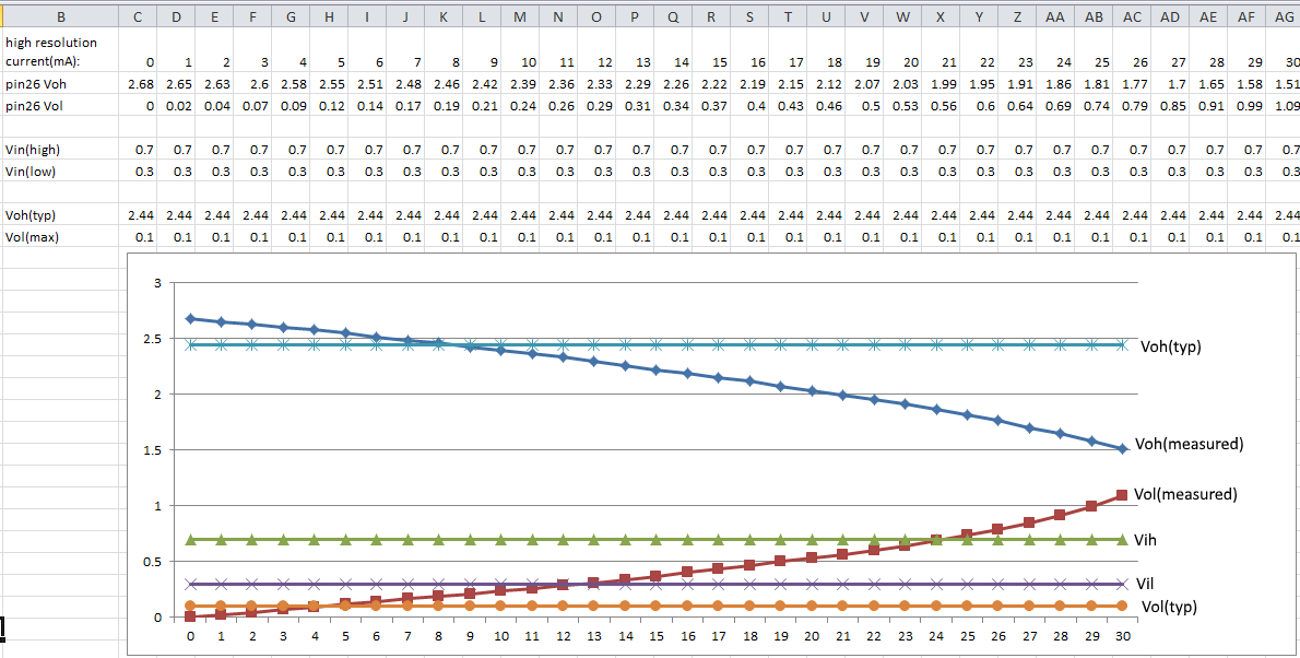
The maximum length of the LED strip ultimately depends on the current handling of the interface circuit. The Omega GPIO pins can sink or source upwards of 30mA - see my post on this at https://community.onion.io/uploads/files/1456930109030-gpio-voltage-curves.png
The interface circuit I designed was specifically for a single 5 meter strip containing 150 RGB LEDs, with a maximum current of around 180mA. The 2N3904 is only rated for 200mA maximum collector current, so a different transistor would be needed for longer strings. The value of R1 is likely to change if the replacement transistor's gain is different from that of the 2N3904.
-
Have you considered using Adafruit DotStar LEDs? They use the Onion's SPI interface and only requires 5 volts. The current draw is programmable through the brightness setting.
I've managed to daisy-chain 5 RGB LEDs off of a single 500mah LiPo battery for about two hours!!
-
Hey!
Well, i "kickstarted" the Omega 2 and this will me my first Project.
My plan ist to turn on an LED Strip beyond my Monitors as soon as my Door is open.The Open Close Sensor is this one: http://www.ebay.ch/itm/Fenster-Tur-Magnetschalter-Magnetkontakt-fur-Alarmanlage-/291609985379?hash=item43e54f4163:g:jS8AAOSwZVlXqb0v
Well i would need a Compatible LED Strip (50+ Centimeters long). Could you send me a Link to one?
And do you have an E-Mail or a Twitter Account so that i could contact you if i get any problems? I would really appreceate that, because as i said this will be my first Project

Have an nice day guys
")
-
@Jan-Gerber, I think replies here (instead of by email) will benefit everyone.
-
Hallo Jan, willkommen im Forum! (welcome in german
)Best is when you look in google and search for "RGB LED Lichtleisten 12V".
And yes, as @fossette mentioned, we share knowledge here in the community. If you have your own project, you can do your own request and ask what you need to know.
The social links, and a lot of other informative links you find on the onion.io page (see footer).
-
Hello Guys, Hallo zusammen!
Ok, ich werde die Konversation hier weiterführen. Wollte nur keinen nerven der nicht daran Interresiert ist, ist in manchen foren so .---.
Ok, i will write here, i just wanted to not annoy anyone here
@Luciano-S Sollte diese hier funktionieren: http://bit.ly/2c3sMy4 (Ist ein Link zu Lightinthebox.com, aber da der eigentliche so unendlich lang war habe ich ihn gekürzt)
-
Yes it looks good. As i see you could use it also without an omega. Connect your Alarm door switch with your strip power source and beside your computer you could control it with the IR Control.
After when you get your omega you can use this tutorial to control your LED Strip.
-
@Luciano-S. said in Using Omega with LED lightstrips:
Yes it looks good. As i see you could use it also without an omega. Connect your Alarm door switch with your strip power source and beside your computer you could control it with the IR Control.
After when you get your omega you can use this tutorial to control your LED Strip.Oh, ok. I will order it and reply here if it worked or not, thank you for the tipp
-
@Janus-Sanders
I would love it if you could email me the details of how you did this. I'd like to build something similar for my first project with my Omega2.Cheers.