Arduino Dock guide is up
-
Hey everyone!
It's taken a lot of blood, sweat, and tears (ok just a bunch of tears) but we've gotten the software and the guide for the Arduino Dock up and running!
The guide can be found on our wiki: https://wiki.onion.io/tutorials/Arduino-Dock/Using-the-Arduino-DockUpdate to the latest firmware (b220) to get all the software goodies.
Have fun and let us know if there are any issues!
-
@Lazar-Demin Cool - that's what I've been waiting for. Looking forward to trying it out and exploring it.
However, given that I don't have a standard Onion Expansion dock (didn't realise one would be needed :-(), would it be OK to just (carefully :-)) solder connections from the mini dock I have in place of wiring up the Expansion dock to the Arduino Dock?
-
@Kit-Bishop Yup, that would be ok. Would be really nice if you can take a picture of it and share it with the community

-
@Boken-Lin Will do.Though it may be a few days away - I've got something else on at the moment.
-
I just tried flashing the bootloader using the mini Dock by trying to wedge some stripped ends of a few Jumper cables (exposed copper strands inserted in the female headers of the minidock and then insert the Omega into the female headers "pinching" the copper strands of each particular wire into the specific female headers.) And usb powering both the arduino dock and the onion on the mini dock independently. But got an error when trying to flash via ssh terminal (using sh /usr/bin/arduino-dock flash bootloader). (Error said rc:-1)
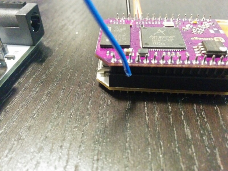
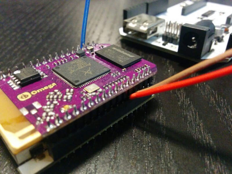
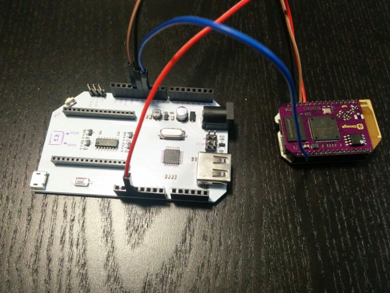
Not sure if there's a way to get 5v directly to the Arduino Dock via the mini Dock or if I have to maybe externally power the Arduino Dock using Jumper cables.
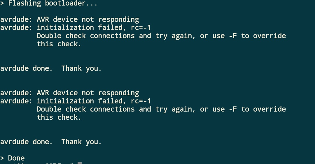
Here's a screenshot of the error which maybe hinting that the connection didn't work (maybe the wires I used didn't make a good connection when I sandwiched them between the mini dock and the Omega pins?)
-
@Maurice Difficult to tell from the photos, but it looks like you only have 4 wires connected though the instructions say that there should be 6 connections
Expansion Dock GPIO 1 -> Arduino Dock Pin 12
Expansion Dock GPIO 6 -> Arduino Dock Pin 13
Expansion Dock GPIO 7 -> Arduino Dock Reset Pin
Expansion Dock GPIO 19 -> Arduino Dock Pin 11
Expansion Dock GPIO 5V -> Arduino Dock 5V Pin
Expansion Dock GPIO GND -> Arduino Dock GND Pin
I may be mistaken, butit looks like there is no 5V or GND connections.Since I too only have a Mini Dock and no Expansion Dock, I am going to have to connect do something like you.
I am concerned about the 5V connection, so my intention is to omit any 5V connection between the Mini Dock and the Arduino Dock. I will power each separately, but connect the GND between the two.
Does anyone have any comments on this?(As an aside, hooking things up would be greatly assisted if we had access to schematics.
HINT HINT HINT to the Omega people :))
-
@Kit-Bishop I tried to power the minidock and Arduino Dock separately using two different micro USB power sources. I'll have to try to powering the Arduino Dock via DC or directly on the female headers. (Ie I'll try not to use the mirco USB port on the Arduino Dock).
-
So I tried flashing both of the Arduino Docks that I received and the first Dock continued to give the error I put in the screenshot above.
The second dock displayed progress bars but I received what looked like three different errors.
On the first Dock the led flickers but the bootloader flash says fail. On the second dock the progress bars appeared but the flashing script said it could not recognize the device signature. The LED on the second dock shut off and didn't flicker. The script eventually went into safe mode....I hope I didn't fry both the boards. Yikes. (Some smoke appeared on one of the Arduino Docks : s)
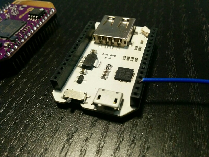
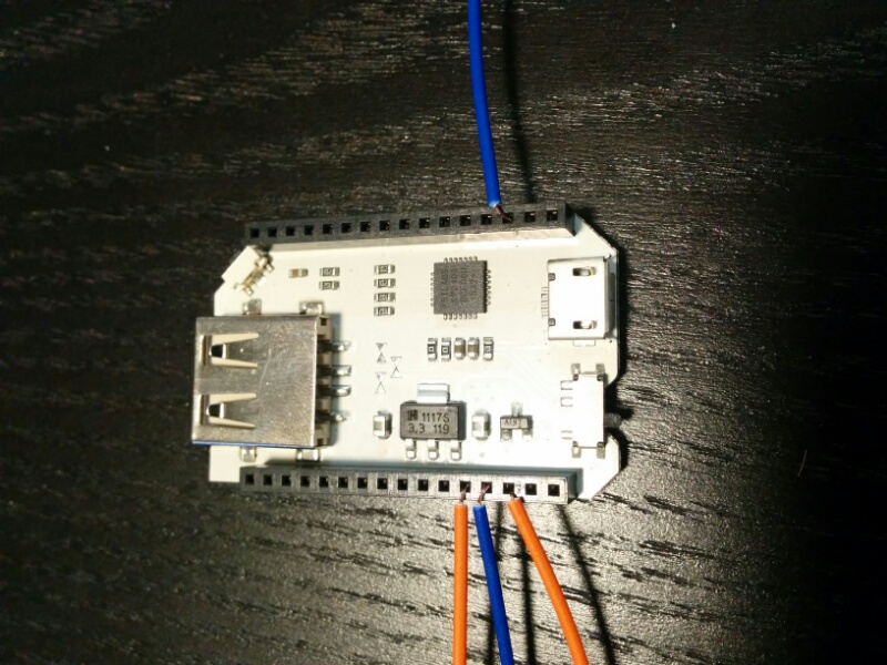
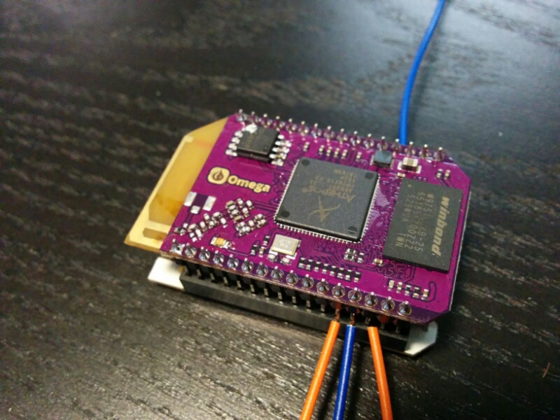
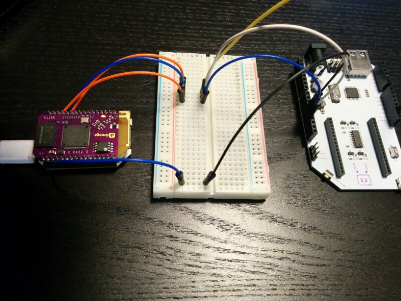
In any case here are some photos. Hope others learn from any mistakes I might have done in this attempt.
Here are screens from the Console
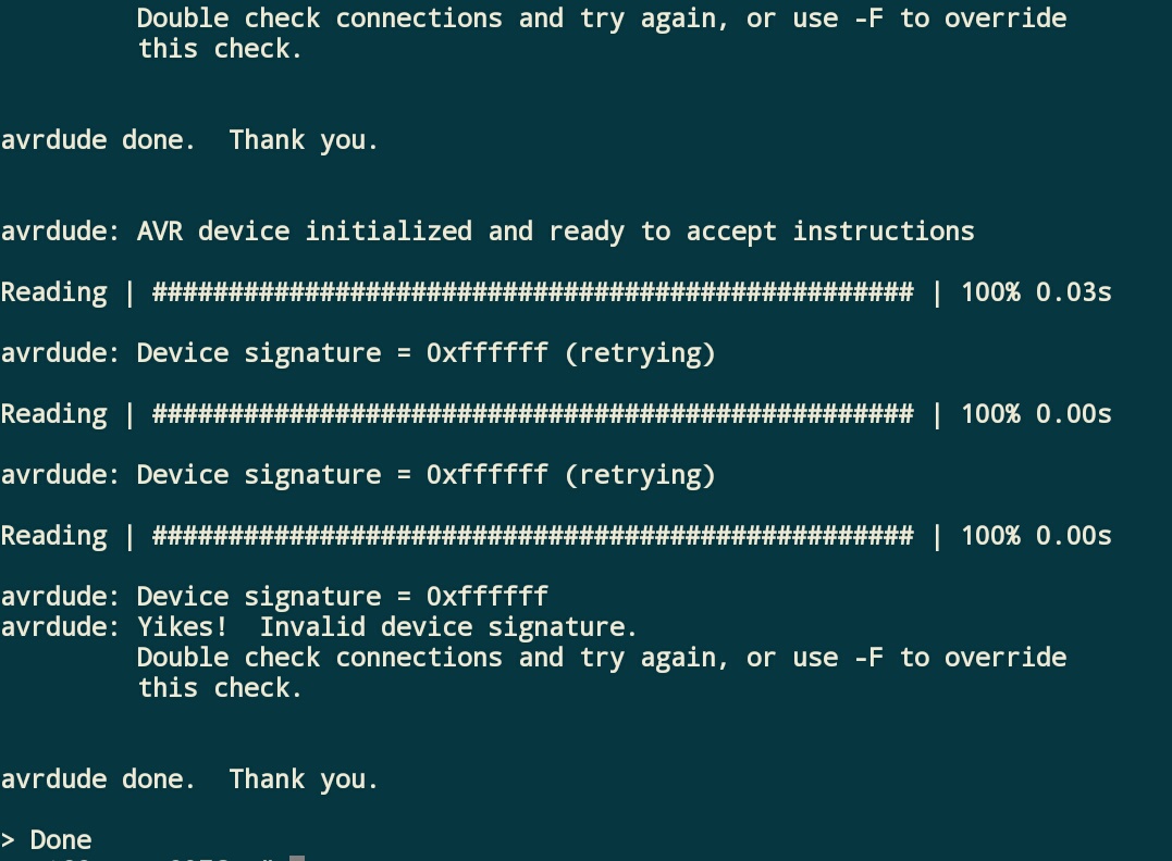
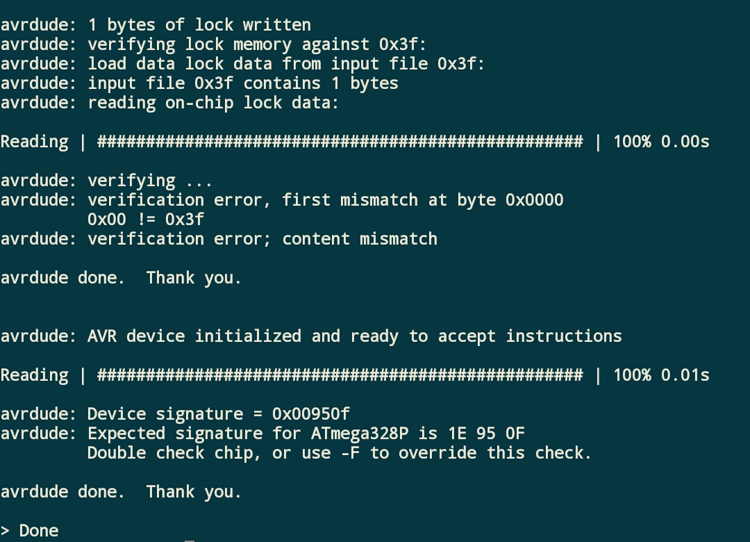
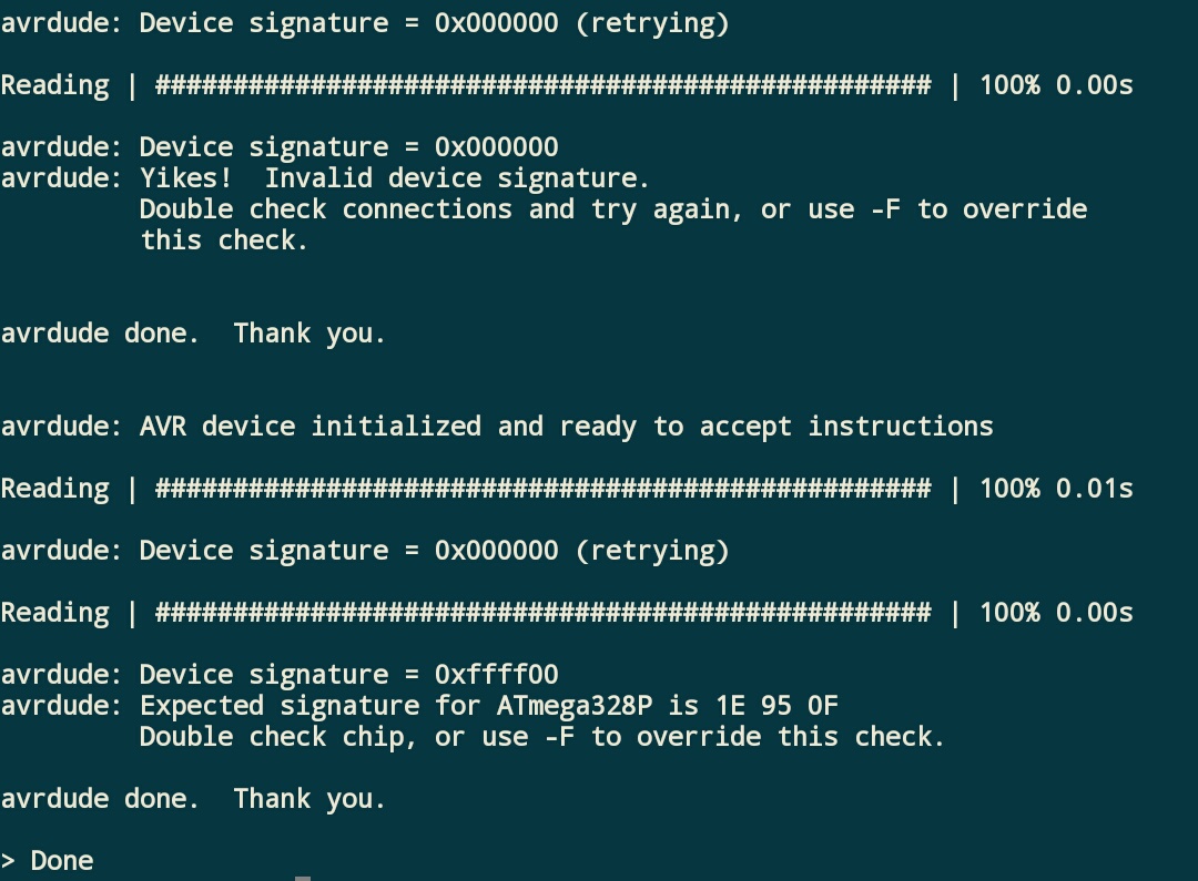
Here are my attempts to wire the minidock
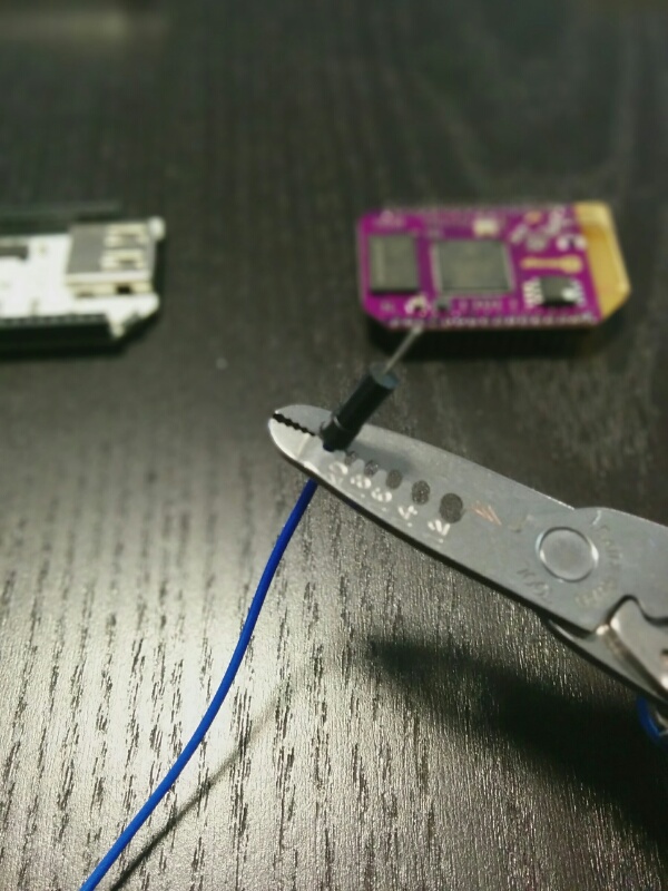
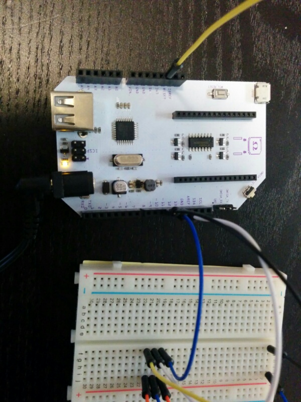
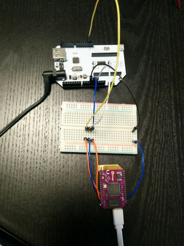
-
If you're using the Mini Dock, the Omega can be used to provide 3.3V to the Arduino Dock, just plug it into the 3V3 Pin. I'll update the wiki to include this info.
@Maurice when establishing communication between two devices like this, it's very important that they share a common ground (as @Kit-Bishop mentioned). Otherwise, there is no "agreement" between the two devices as to what defines a low signal (a 0 in binary) and what defines a high signal (a 1 in binary). It's likely that the Arduino Dock and Omega are misunderstanding each other.
Try running the 3.3V and GND to the Arduino Dock and trying again. Let me know how it goes!
-
I have a couple of questions in relation to all of this.
First so you understand what I am currently doing:- I don't have an Expansion Dock I only have a Mini Dock and an Arduino Dock
- I have an Adafruit PowerBoost Shield with 2000mAh Lithium battery
- I plug the Omega in to the Arduino Dock
- I plug the PowerBoost Shield in to the Arduino Dock
- I only ever communicate with the Omega using WiFi
Thus, always have power that can be switched on and off as required and no mess of cables everywhere:-)
This all works without any problems and implies to me that the Omega is powered by the 3.3v from the Arduino Dock.
First question:
- Is this OK and safe?
Next, I note in the instructions that once the Arduino Dock is set up, a sketch can be loaded on to the Arduino Dock using:
- sh /usr/bin/arduino-dock flash <hex file>
but for I note that for the initial set up:
- this is basically the same as what we initially need to do to initially set up the Arduino Dock, i.e.:sh /usr/bin/arduino-dock flash bootloader
- and there is no other communication between the two for setup
These two together imply to me that when the Omega is plugged in to the Arduino Dock they are already connected as covered in the wiring instructions and that consequently no additional wiring is required and the whole procedure can be carried out without the separate wiring.
So my second question:- Am I correct about this, or have I missed something?
-
@Kit-Bishop Yep, what you're doing is safe and ok. You can also power the Omega + Arduino Dock with a micro usb. And when using the Arduino Dock you can only communicate with the Omega via WiFi (ssh and console) even when the micro usb is plugged in.
The extra wires are only needed for the Inital Setup (now on it's own wiki page). Once you complete that, there is no need for any extra wires.
The Omega can then use the Arduino Dock to flash the ATmega chip with Sketches. You can use the command you have above or you can use the Arduino IDE to wirelessly have the Omega flash the ATmega chip (probably the quicker option).
-
@Lazar-Demin Cool
 Thanks for the quick response
-
I'm getting a failure when I try to enter the password to upload the sketch. Error message is ash: merge-sketch-with-bootloader.lua: not found. I flashed the board and I thought is said it was ok. Ideas?
Thanks,
Russ
-
I try to burn the bootloader, all my connections seems OK but I always have this message:
root@onion:~# sh /usr/bin/arduino-dock flash bootloader
Flashing bootloader...
avrdude: AVR device not responding
avrdude: initialization failed, rc=-1
Double check connections and try again, or use -F to override
this check.I double check connections, everything is fine. What can I do?
-
@Lazar-Demin just tried flashing the dock and it worked for one of the docks
 one of the docks continued to display the error.
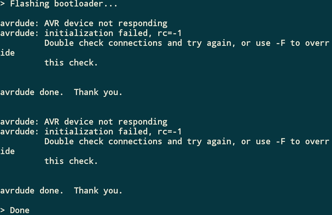
For the dock that did work:
I wired the dock as you suggested with 3.3v and GND wired to the dock.Function SPI MISO -> Mini Dock and Omega Pin 1 -> Arduino Dock Pin 12
Function SPI SCK -> Mini Dock and Omega Pin 6 -> Arduino Dock Pin 13
Function SPI RESET -> Mini Dock and Omega Pin 7 -> Arduino Dock Pin Reset
Function SPI MOSI -> Mini Dock and Omega Pin 19 -> Arduino Dock Pin 11
Function VCC -> Mini Dock and Omega Pin 3.3V -> Arduino Dock Pin 3.3V
Function GND -> Mini Dock and Omega Pin GND -> Arduino Dock Pin GND
Here are some photos of the wiring.
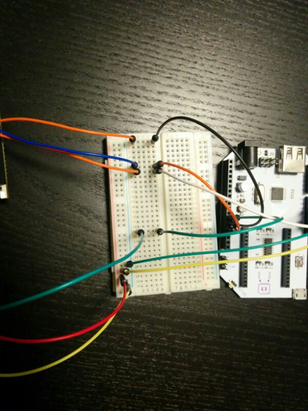
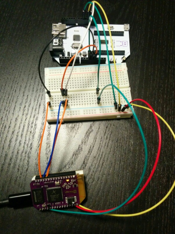
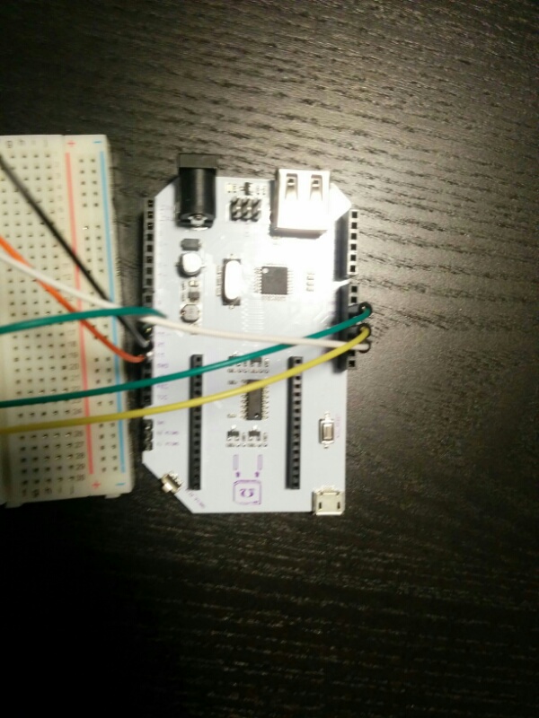
I then powered the minidock which and ran the script on the Omega via ssh terminal.
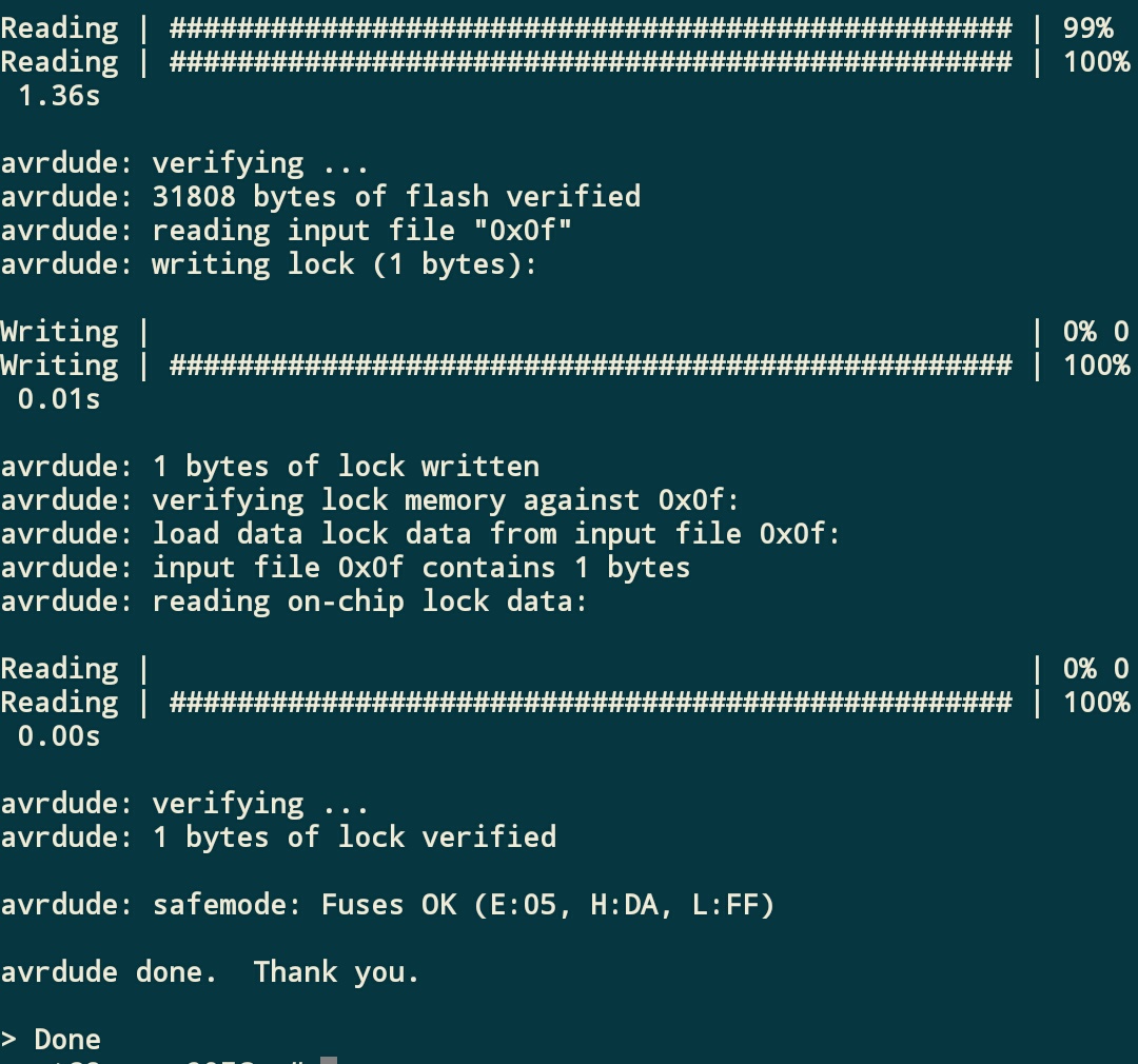
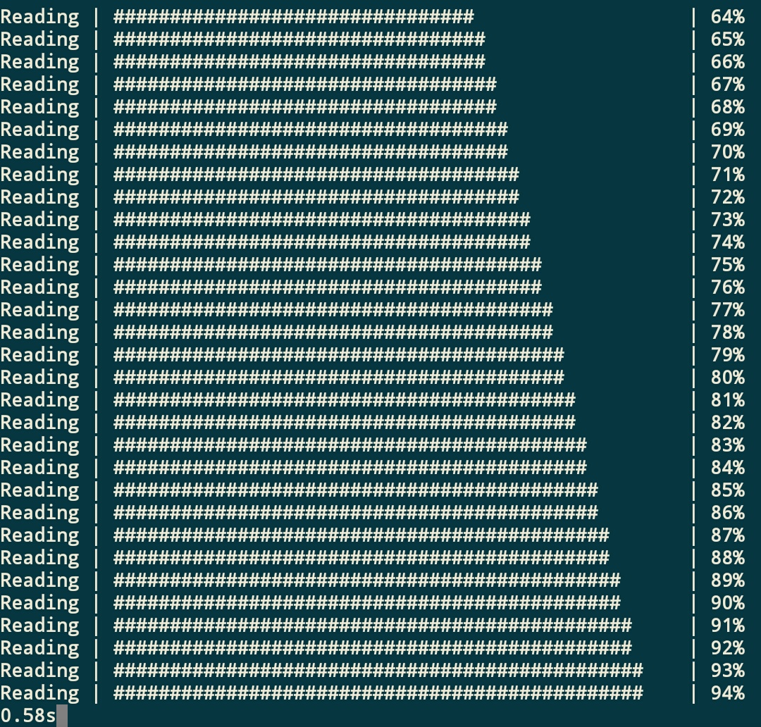

So for me. One of the Arduino Docks works but but it looks like the other one does accept the bootloader (might be fried.)
-
@Russ-Terrell Yeah, that message will show up but the flash should still work. Try enabling Upload verbosity in the Arduino IDE settings and posting the message.
-
@Tchernobil Are you using an Expansion Dock? Can you post some photos of the setup?
-
@Maurice glad that it worked and sorry to hear that one of the Docks is non-responsive

-
I use the Espansion Dock. You can see a video of my setup here:
http://www.grafigne.com/files/wires_arduinodock.mp4
How can I test if my arduino dock is defective?
-
@Tchernobil Can you try following the 'Using the Omega + Expansion Dock with the Arduino Dock ICSP Header' procedure from the Arduino Dock Initial Setup Guide?
Let me know how it goes.