[RESOLVED] Relays sticking?
-
I mean physically, how well-seated are the relay expansion modules plugged into the pass-through socket on the expansion dock?
Short of a circuit design problem or defective parts (I am not yet convinced of either, just trying to chime in to help), another area you can turn your attention to, to try to solve the problem, is to see if the stuff is physically making contact for all the signals.
If you have an intermittent connection, something like what you are seeing is possible.
-
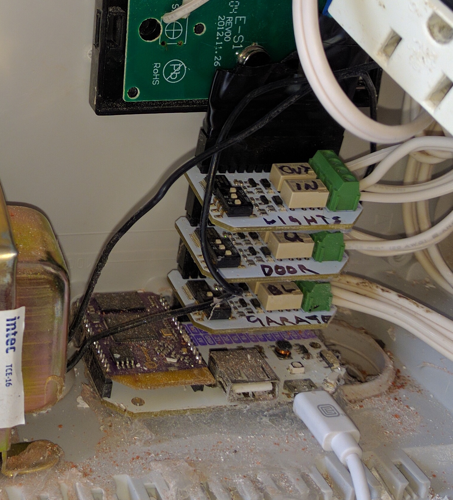
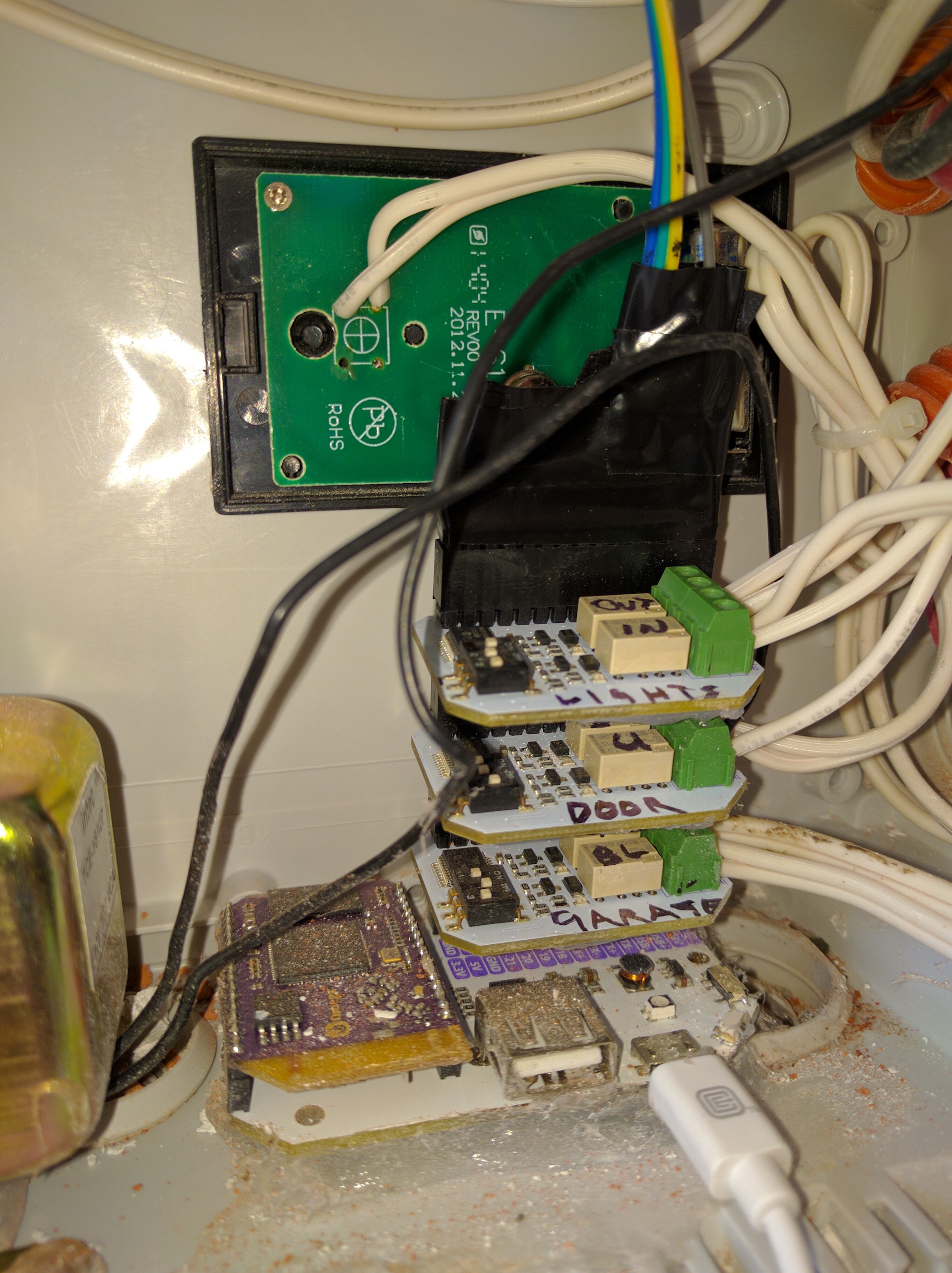
Ok, here is my setup. As you can see, there are 3 expansions stacked one on top of the other.
The problem with the lights expansion occurs no matter if it is on top or on the bottom. Tried 2 others as well. I will try 2 others I have later on tonight and hope that it solves the issue.
-
It is worth noting, that I put silicone on the base of the relay expansions to make sure they would not touch. In reality it was because I was tired of getting shocked when accidentally touching!
-
Okay gotcha.
- If you've already done the trouble-shooting of moving the expansions around and they still stick, I think that rules out the possibilities I suggested.
- I don't think this is the cause of any of your troubles, but for this installation you may want to consider printing out a 3D case for the Omega and dock, at least to keep some of the stuff from getting dust and dirt on them. I don't have the link handy, but I did get one of the cases I found online printed recently, and the fit was near-perfect first shot. I wound up not needing the top portion, but if I did it would've needed just a bit of tweaking to allow the relay expansion to sit nicely.
-
Jim,
Thanks. The dust will be removed. The case is a plastic case I bought specifically for storing the omega and the other bits and bobs. I used silicone to stick the Omega to the plastic case. Either way. Thats 3 relays that don't work. I wonder if perhaps I got a bad batch. I bought another 10 today so I hope that these will not have problems. I will test with another 2 relay expansions I have today. See what happens.
-
The most common cause of relays sticking is because of micro-welding of the contacts caused by arcing when the contacts close/open.
This can occur even when the current being switched is within the rating of the relay.
This micro-welding can usually be broken by suitable mechanical shock - i.e. giving them a knock")
When the circuit being driven is subject to an increased current surge on making contact - e.g. when switching an incandescent bulb, the initial cold current can be significantly greater than the normal operating warm currentNormal suggestions to minimise this micro-welding are:
- Try driving the relay with a higher current so the relay operates faster closes faster to reduce possible arcing time - though I don't see how this could be done with the Relay Expansion
- Use a relay with a stronger return spring so it opens faster to again reduce arcing time - again not possible on the Relay Expansion without physically replacing the relays
- Use some suppression across the contacts to reduce the arcing - e.g. connect a capacitor across the contacts (i.e. from the In to OUT connections) - I am not enough of an electrical engineer to suggest a suitable value for the capacitor but it should have a voltage rating high enough for the circuit being switched and if switching AC it should NOT be an electrolytic capacitor.
Finally, if the problem really is being caused by the relays on the Relay Expansion not being rated highly enough for the circuit being switched, you could use the Relay Expansion relays to switch separate external relays that have a higher rating
-
@Kit-Bishop Kit,
They all seem to work again after "giving them a knock".
I will read a little on the capacitors to see if I can find a suitable value as I know very little of the matter as well!
Thanks for the suggestion.
-
Ok, I had a chat with my father, who is an old engineer and used to work in BT in the 50's, he told me of a trick they had back then. Apparently they let the relay weld and would "unstick" it, and do this a few times. He claims this would even out the surface and create a bigger surface of contact so less micro-welding.
Odd no?
Well, I tried this, and after 5 or 6 times the relays no longer locked!
All is well now
Thanks guys.
-
@Samuel-Mathieson said in Relays sticking?:
...Apparently they let the relay weld and would "unstick" it, and do this a few times...
I'm not sure if I understood right, you took the solder Iron and made the 8legs of the relays "warm" that the solder ran back to the hole of the circuit board from the extension? Without adding new solder?
-
No, he let the relay stick a few times and it worked itself out. Interesting!
Glad you're on your way. BTW, not sure your level of solder skills, but I like two of the suggestions above and would try either of them if you get more problems:
- Replace the relay with a pin-compatible heavier-duty one (or)
- Have the onboard relays drive the coil of heavier-duty relays
-
Amazing, glad to hear to worked out!
@Kit-Bishop I had no idea that was even possible!@Samuel-Mathieson make sure to post your project when it's done, I would love to see the final result.
-
@Samuel-Mathieson said in Relays sticking?:
Should I use a diode on the contacts?
Thanks for any help.
Try throwing a diode across the coil of the relay eliminating contact bounce as the culprit.
-
There are already rectifier diodes on the Relay Expansion, one for each relay coil. They can be seen in the schematics here, see components D3 and D5.
-
@Gabriel-Ongpauco Nice schematics
-
@Gabriel-Ongpauco @Guest @Samuel-Mathieson Yes, the Relay Expansion does already have diodes across the coil. This will reduce bounce due to surges in the coil current but won't necessarily eliminate it. The way to reduce arcing when the contacts make/break is to use capacitors across the points themselves - see: http://www.industrologic.com/mechrela.htm for an example.
-
Its funny how things worked out. I did think about getting another relay to activate with the relay expansion relay but in the end I decided that would beat the purpose of a relay.
I did not think of replacing the relay expansion relays. I think that would be a good way to go if I see more problems in the future.
Thanks again everyone.
-
Some background information about the reason for the "arcing" and "micro-welding" described above:
It is usually caused by inductive loads, like electromagnets, motors, transformers - pretty much anything that is based on a coil of some kind.
Coils have a surprising property - the current that flows through them cannot suddenly change. So if you have a motor running on, say, 200mA, and your relay breaks the circuit, the current needs some time to ebb, it cannot go from 200mA to zero at once.
But how is this possible with the circuit open? There's only one way - the voltage between the now open contacts will rise so high that the current can flow through the air between the contacts! High voltage can ionize air to make it conductive. In small scale this is called an electric arc, in large scale it's called lightning...
In both cases, it's very hot, and happening between relay contacts causes contact material to melt and micro-weld. Even if the relay spring is strong enough to rip the contacts apart eventually, and the relay does not stick, this ruins the contacts over time, and should be avoided.
But how?
If the circuit is DC, it's simple. You just need a so called flyback diode over the inductive load which allows the coil to discharge its energy without generating high voltage.
Note that this is also essential when driving a relay (a coil, too!) from an electronic circuit. If you forget the flyback diode, the high voltage will disturb or even destroy the electronics. See D3 and D5 on the Onion Relay Expansion schematics.If the circuit switched by the relay is AC, a diode does not work (would short-cicuit half of the time and destroy itself). Instead, use a RC snubber, a capacitor in series with a resistor. For use with 230V AC, ~20..100nF/400V capacitor and a 100Ω/2W resistor works. The snubber consumes some energy of it's own, that's why the resistor should be a 2W type, and will produce some heat. There are also RC snubbers in a single part, like this one.
Hope this help to tame your relay circuits
")
As a side note: there are circuits where the high voltage caused by breaking the circuit of a coil is the desired result - ignition in combustion engines, electric cattle fences...
-
@Lukas-Zeller Some very good information particularly in relation to inductive loads.
I also have some concern in relation to the resistive load of incandescent light bulbs at turn on time.
The original poster (@Samuel-Mathieson ) indicated that he was driving 20W @ 120Vac - this (when the bulb is warm) equates to about 166mA - this should be within the capabilities of the relay.
However, if the light bulbs are typical tungsten filament bulbs, they can have a cold resistance of around 1/15 th of the warm resistance. So the current at switch on from cold could be as high as 2.5A (2500mA) briefly - this could potentially briefly exceed the relays rating
-
If it is possible and does not affect the operation of the circuit, place a delay in the opening of the circuit allowing the inductive loads to subside then opening the contacts under non inductive load.