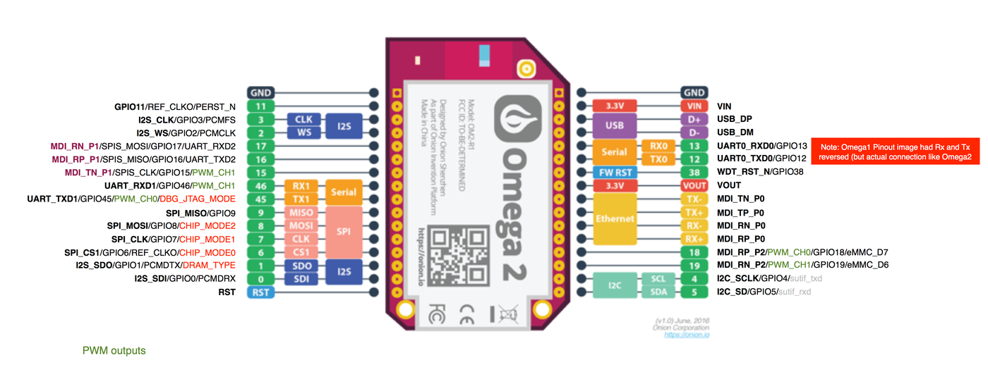
Omega2 annotated pinout (including MT7688 pin names)
-
Here's an annotated Omega2 pinout which lists all possible pin functions and the actual MT7688 pin names (in boldface) as found in the datasheet. The red ones are those signals sampled by the MT7688 at reset to determine operation mode, so these must not have heavy load and/or pullup/downs.
I did that pinout for deciding which pins to use for what when designing a PCB for a Omega2 based project of mine. I hope it might be useful for others

[Update: the latest version, covering Omega2 and Omega2S, including additional info about pins with bootstrapping functions, can be downloaded here]

[Update: in case you are looking for a similarily annotated pinout for the Omega2S, look here]
-
@luz Why is it so blurry?
-
@WereCatf said in Omega2 annotated pinout (including MT7688 pin names):
@luz Why is it so blurry?
Maybe because luz's screen had a little dust on it when he took his screen capture. Lol!!!
Kidding aside, I suspect that the center of the image (from Onion) has been resized by a little %, and it does give an impression of loss of sharpness. The black writings on both sides are perfectly sharp.
-
I guess they took just a low resolution picture and made the writings new. That's why the writings are perfect sharp.
-
@Luciano-S. said in Omega2 annotated pinout (including MT7688 pin names):
I guess they took just a low resolution picture and made the writings new. That's why the writings are perfect sharp.
The pinout-diagrams in the official documentation are perfectly sharp, Luz messed up the sharpness. I am not trying to diss on him, quite the contrary, but I would hope he'd find it in himself to fix the blurriness.
-
@WereCatf @Luciano-S @fossette LOL, it wasn't meant as a piece of art, just some info

I did this a few months ago, when the only Omega2 pinout I could find was the web image in the Kickstarter campaign, which had that somewhat limited resolution. I put the image into Pages.app and added the annotation around. The result was a PDF, but to post it today I converted it into a reasonably sized png. If anybody wants the .pages to improve it, just let me know…
-
@luz said in Omega2 annotated pinout (including MT7688 pin names):
@WereCatf @Luciano-S @fossette LOL, it wasn't meant as a piece of art, just some info

What?! Are you sure? I could've sworn I saw some inspiration being taken from Mona Lisa!
-
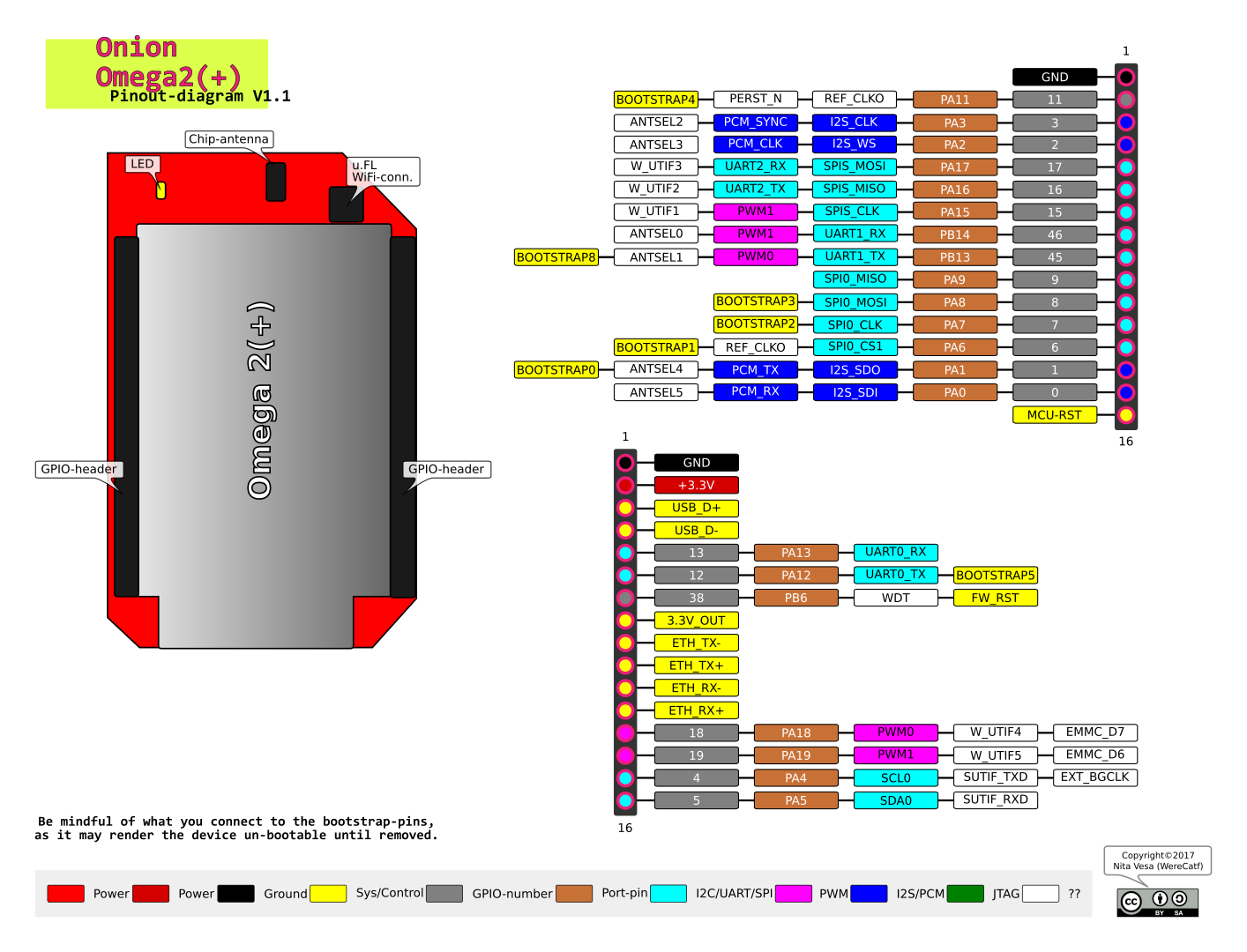
Here is my take on a pinout-diagram. I specifically wanted to mark all the bootstrap-pins clearly, in the hopes that it'd be easier to avoid messing with them unnecessarily, and I wanted a higher-resolution diagram, that can be printed out on paper, if needed.

The SVG-file is, as usual, available on my github-repo ( https://github.com/WereCatf/SBC-pinouts )
-
@WereCatf & @luz , in this occasion i would like to ask about the "older" Mini-Docks not working with Omega2 & 2+.
-
Could be that a bootstrap-pin is shorten and not let boot the omega2+ ?
-
Would a uboot change solve it? (probably a older one?)
I bought my omega 2+ to use with a mini-dock i already had from onion.io store.
@administrators how do we have to proceed with this fact?
-
-
@Luciano-S.
Aye, I checked the schematic and there is a pull-down resistor on UART0_TX. As my diagram shows, UART0_TX is also one of the bootstrap-pins.You could try removing the pull-down resistor R84, which should allow the Omega2 to boot normally.As for u-boot: no, the bootstrap-pins are a hardware-feature and they get applied before u-boot is loaded. They determine things like what mode the SoC boots in, whether the PCB has DDR1 or DDR2 and stuff like that, and these things obviously have to be configured before any software can be executed in the first place.
-
@Luciano-S. I was looking at the wrong bootstrap-pin in the PDF earlier, UART0_TX should be pulled down, so the pull-down resistor doesn't matter. I was looking at the boostrap-pin on UART1_TX, which is the opposite.
-
@WereCatf Thanks for your clear and detailed pinout diagram. Wow, you had me excited for an hour re-considering a hardware fix for the old mini docks ... Actually, the Omega2 boots fine on those docks, there just isn't any communication to/ via the Omega2's RX0 pin - such as unresponsive keyboard, can't use Busybox, etc. Luciano and I wrote about our observations HERE and HERE.
I am curious, could/ does the Omega2 boot-strap determine which pins are the serial Tx and Rx?
-
@Ken-Conrad Does your mini-dock match the schematics at https://raw.githubusercontent.com/OnionIoT/Onion-Hardware/master/Schematics/Omega-Mini-Dock.pdf ? Those are a year old and as far as I understand, they should match the old mini-dock.
-
@Ken-Conrad Oh, and no, the UART-pins are fixed and cannot be moved to other pins as no other pins have a UART0-mux. So no, the bootstrap-pins can't do that.
-
@Luciano-S. said in Omega2 annotated pinout (including MT7688 pin names):
@administrators how do we have to proceed with this fact?
I made also a ticket in this (mine) request.
-
@luz What PCB did you design? Care to share?
-
@Victor-Tagayun it was a small mainboard hosting the Omega, a ethernet jack, a 4.5..39V to 3.3V converter (single part, integrated), a RS485 serial, two multiplexed i2c connectors and a level shifter for WS281x LED chains.
If anybody is interested in this very particular combination of features, just let me know

This is part of a larger project, which I will publish as soon as all the hard- and software parts work together as intended, from laser cut wood to WS281x kernel driver using MT7688 PWM…
-
@WereCatf said in Omega2 annotated pinout (including MT7688 pin names):
I was looking at the wrong bootstrap-pin in the PDF earlier, UART0_TX should be pulled down, so the pull-down resistor doesn't matter. I was looking at the boostrap-pin on UART1_TX, which is the opposite.
Can I please ask what this PDF file is?
-
@György-Farkas A PDF-file is short for "portable document format" and is a file format used to present documents in a manner independent of application software, hardware, and operating systems. Each PDF file encapsulates a complete description of a fixed-layout flat document, including the text, fonts, graphics, and other information needed to display it. -- https://en.wikipedia.org/wiki/Portable_Document_Format
-
@WereCatf said in Omega2 annotated pinout (including MT7688 pin names):
@György-Farkas A PDF-file is short for "portable document format" and is a file format used to present documents in a manner independent of application software, hardware, and operating systems. Each PDF file encapsulates a complete description of a fixed-layout flat document, including the text, fonts, graphics, and other information needed to display it. -- https://en.wikipedia.org/wiki/Portable_Document_Format
Really?!

@WereCatf said in Omega2 annotated pinout (including MT7688 pin names):
I was looking at the wrong bootstrap-pin in the PDF earlier, UART0_TX should be pulled down, so the pull-down resistor doesn't matter. I was looking at the boostrap-pin on UART1_TX, which is the opposite.
Can I please ask what that PDF file is?