Omega2 u.fl external antenna usage
-
@Marc-Juul said in Omega2 u.fl external antenna usage:
Hm. Did I ask a stupid question or does no-one known?
There are no stupid questions ... just stupid answers

Do you have a external antenna? Did you connect it? What happens? Maybe nobody who used external antenna saw your question !
-
@Luciano-S. I do have an external antenna and I tried it out weeks ago and noticed absolutely no difference in WiFi-signal strength.
-
Indeed, it's going to be hard to tell anything with an antenna; you'd either need a carefully designed experiment, or RF test equipment. And only the later or detailed examination of the design would lead to a conclusion that can really be generalized.
-
@Chris-Stratton I disagree. Putting my hand in front of the antenna on another WiFi-device and cupping my hand behind the antenna shows a very clear difference in the signals when viewed with iwconfig, with hand in front of the antenna worsening the signals and cupping my hand behind the antenna, in the opposite direction from the router, shows an improvement. Alas, with the Omega2 I saw no change when the external antenna was connected and this leads me to believe that you do need to cut some trace to enable it. Or my Omega2 is faulty.
-
I actually just went and tried it again and sure enough, connecting an external antenna has literally zero effect. Interestingly, just simply placing my finger under the chip-antenna, on the other side of the PCB, improves signal-level from -53dBm to -32dBm! I've been having poor WiFi-performance with my Omega2 from the moment I got it, so it would be nice to use an external antenna.
-
According to the documentation I found here, just plug in an antenna and you are good to go (bold text is mine):
Connect an external antenna to the Omega’s male surface-mounted U.FL connector. An external antenna can be used to extend the range of WiFi connectivity or provide a very directional signal. If a U.FL antenna is plugged in, it will be used as the default antenna, no setup required.
-
Perhaps it's worth enumerating some possibilities:
- The onboard antenna is connected and the connector is not; a surface mount resistor would have to be moved to change that (or the reverse)
- The connector and onboard antenna are in parallel; this may be "interesting" from an RF perspective and it may be hard without test equipment or study to differentiate "works a little bit better" (or doesn't) from "works as intended"
- The connector has a built-in switch that mechanically disconnects the on-board antenna when something is plugged in
- There's an electronic antenna switch. I doubt this, but it's possible.
- The MT7688 has a cousin with two antenna ports, but it seems like we'd have heard if this was in use, and there'd likely be driver issues.
- It's supposed to work one way, but the board someone has on their bench has a defect
One of these is the answer, and it probably can be determined which. But just plugging in an antenna to see what happens won't yield a real answer on which actions can be soundly taken.
-
WereCatf - I'd guess by now you tried some aluminum foil under the Omega2 chip antenna, in place of your finger. Your post and this thread stirred me to experiment with the U.FL connector, add an external 2.4Ghz antenna then measure the signal strength with the Android phone app, Wifi Analyzer.
I disagree with some options and information expressed here and in the Onion resources. In my experience the onboard antenna doesn't work in unison with an external antenna, if fact they are designed to stand alone or be disconnected before you connect the external antenna, as done in these router antenna hacks TP-Link MR3020 and TP-Link WR703N. I've used these and they work.
Today I found that -
- yes, the RF feed for the U.FL socket is wired in parallel with the onboard chip antenna
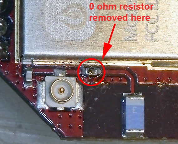
- the onboard chip antenna is connected to the RF output by a tiny 0 ohm resistor/ jumper
- You can 'disconnect' the chip antenna by desoldering the 0 ohm resistor (I used an iron at 550 degrees F for ~20 seconds). For my eyes a magnifying lens was a must, and my soldering iron has a very fine point. There isn't much room on the board around this part ... A fine pointed knife could be used to cut this part off, refer to my photo. Done carefully, The change will be non-destructive and reversible with a small blob of solder.
-Note that you will ALWAYS want to have either the external or chip antenna connected whenever the unit is powered, otherwise you risk damaging the RF circuit of the unit!
-For the external antenna testing I used a very directional 2.4Ghz PCB Yagi antenna with a maximum 11dBi gain. No testing outside yet - it rained all day. I measured the Omega2's Wifi signal indoors through two (wooden) floors, past a fluorescent fixture, etc. Compared to the stock Omega, there was no signal change with both antennas connected. After the chip antenna was removed from the RF circuit, the external antenna on the Omega2 boosted the signal by 10 to 15 dBm. I'll follow-up after I have tested some other antennas.

-
@Ken-Conrad I figured they were in parallel, but having no background in radio-stuff I didn't know if it's supposed to work or not. I'm glad you took the time to test things out!
-
@Ken-Conrad you're a hero! Thank you so much!