Access point not found
-
@WereCatf I think your comment highlights the problem. 70 cents works for you and a few hundred Euros doesn't work for poor @patrick-seb
No offence to Patrick but I hope his Omega is faulty and that normally a power supply costing a few hundred Euros is just about adequate.
"Too long or too thin" is a pretty poor position in my book.
-
@Costas-Costas said in Access point not found:
"Too long or too thin" is a pretty poor position in my book.
No, it's not. Ask any professional EE and they'll tell you that wiring matters. The length and the thickness of the wiring affects the voltage-drop caused by them -- the longer the wire and the thinner the wire, the bigger the voltage-drop.
-
@patrick-seb are you an EE?
Here is my set up with an AMS1117. Around 25 cents when bought in bulk, or 50 cents if you just want one delivered to your door. Swap you?
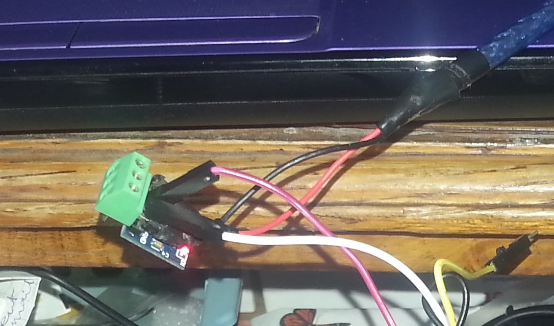
-
@WereCatf said in Access point not found:
The length and the thickness of the wiring affects the voltage-drop caused by them -- the longer the wire and the thinner the wire, the bigger the voltage-drop.
That is what i was reading about the length & thickness of the USB cables. This is quite a poker game if there are just cheep lousy cables around.
-
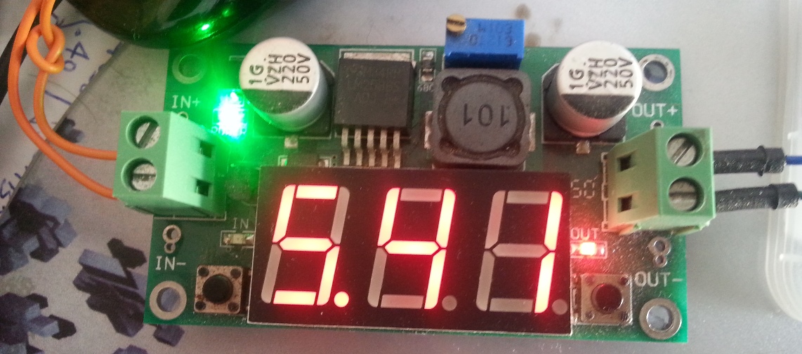
@patrick-seb this is another one of my Omega power supplies. The feed is coming from a power adaptor that can be set to 3 / 4.5 / 5 / 6 / 9 or 12V. I have it set at 9V and the picture shows a setting of 5.41V on the step down regulator, which is fed into another AMS1117.
For the Omega to work, with precisely the wire length and gauge I have, it has to be exactly this magic (9V to 5.41V to 3.3V). Do you play poker?
-
@Costas-Costas Mate, all you're doing is arguing with people who know better than you. You clearly don't have a fucking clue on what a voltage-drop means or how wire-thickness and -length come into question. I have that exact same drop-down converter as you have in the picture, and lookit it here:
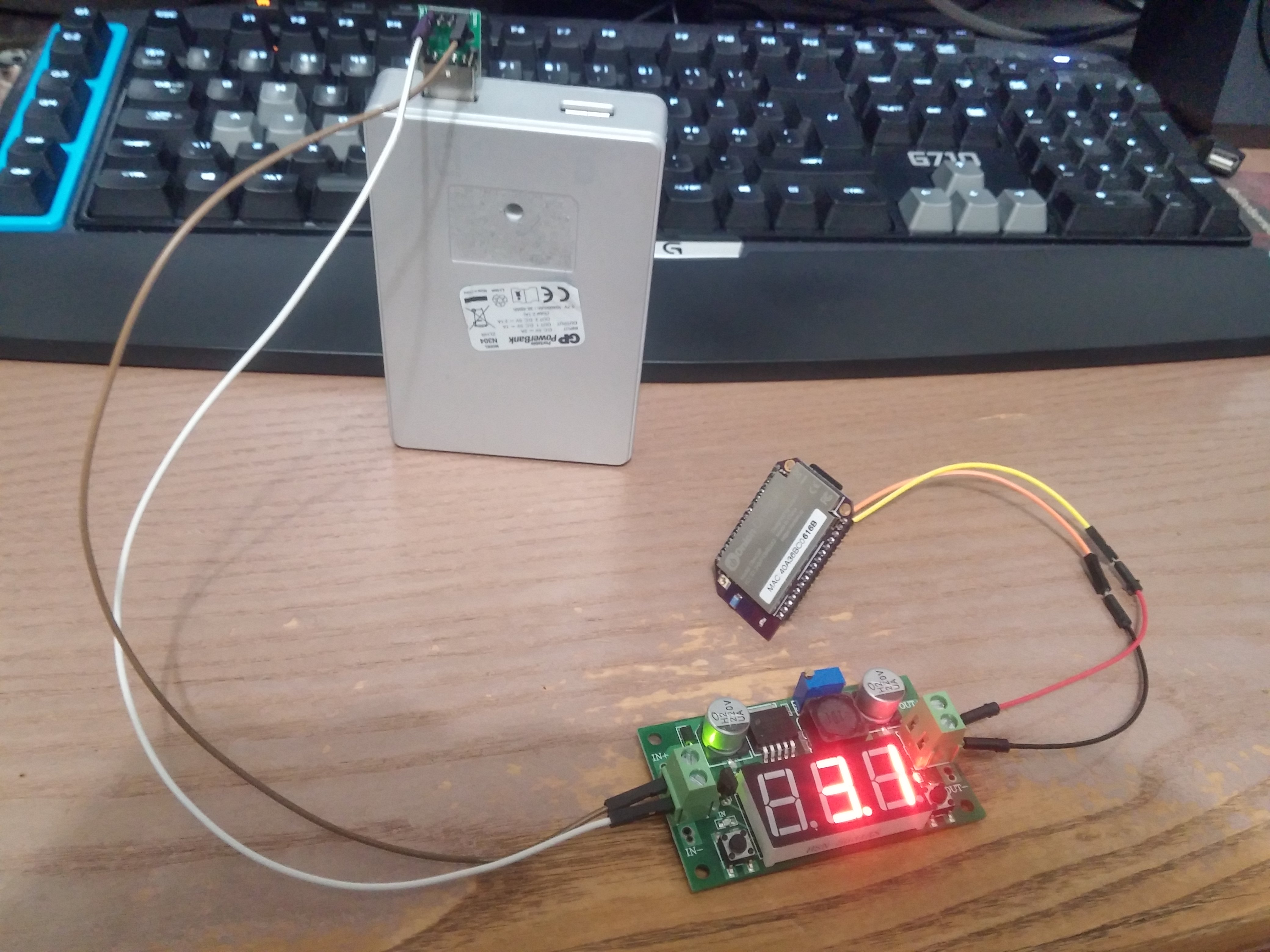
With lengthy, thin wires from the power-supply to the converter the Omega2 fails to stay powered-on, the LED goes off after a bit. Then, I removed the wires, reducing the voltage-drop between the power-supply and the buck-converter, and what do you know? The Omega2 works fine!
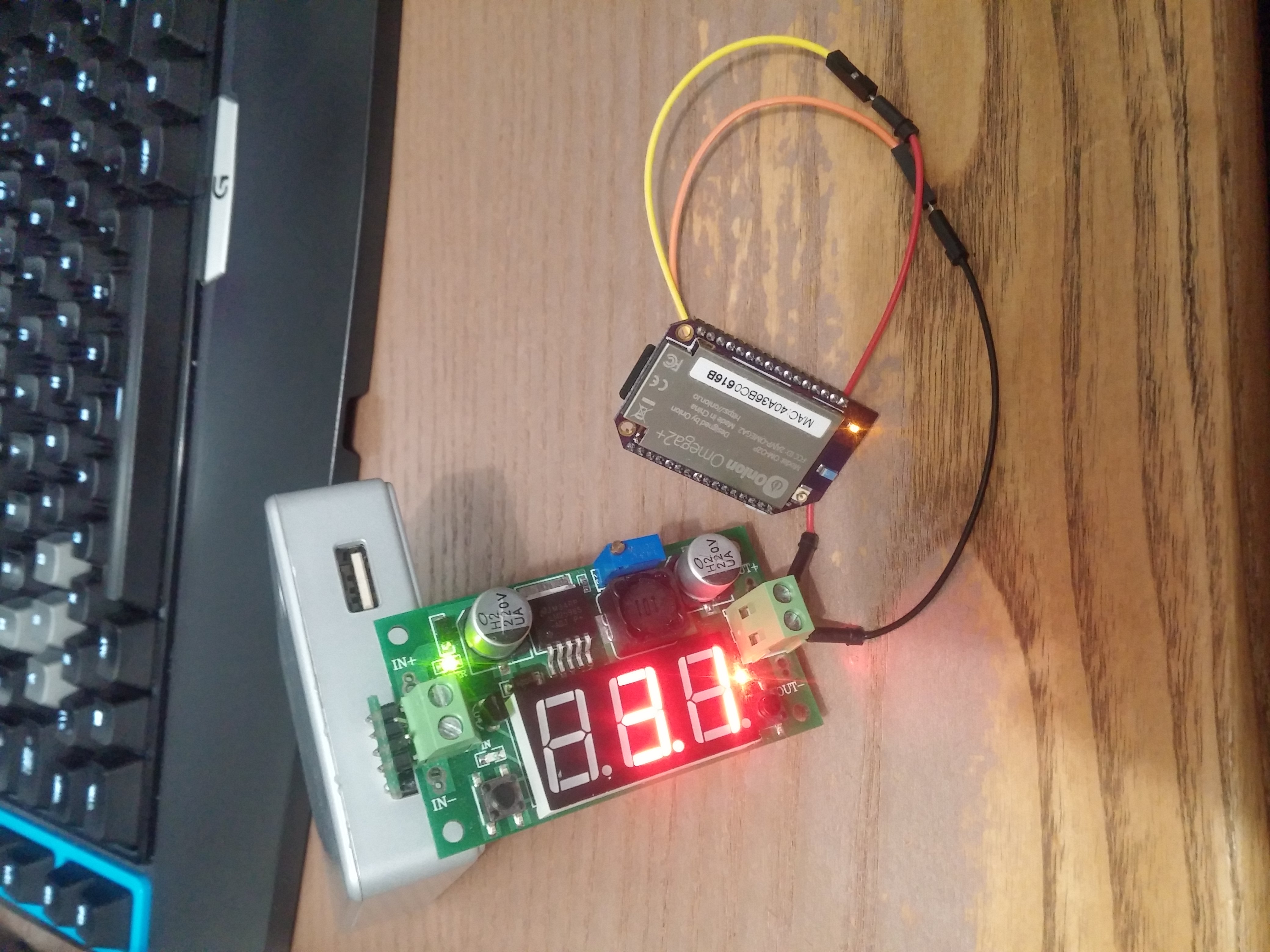
Shall we play that poker now?
-
@patrick-seb ignore the profanities and do let us know how you get on.
-
FWIW I have not seen good results with these LM2596 modules and MT7688 boards. What I don't yet know is if the LM2596 itself responds poorly to pulsed loads, the capacitors on the regulator boards are underperforming due to cost-cutting, or the issue is with the upstream supply to the module.
But short leads are definitely a good idea, for reasons of inductance as well as resistive loss.
The challenge of an MT7688 system is not time-average or "getting hot" power - absent problems that is quite low - but rather pulsed loads that double the baseline load.
-
@WereCatf Pololu.com explains LC voltage spikes and drops in longer power leads pretty well here - https://www.pololu.com/docs/0J16/all . Seems when Omega2s have flaky performance there could be supply power filtering issues.
Also, in my experience the cheapest Chinese wire leads have at best three or four strands of the thinnest possible recycled copper "wire".
I'll take some well designed testing over Vegas odds, any day.
-
@Ken-Conrad I'm not sure why you're telling me that, when I'm the one who was saying all along that wiring matters.
-
@WereCatf I agree with you and your post, although I am not here to choose sides. Did you have a chance to look at the www.Pololu Support pages? The take-away from their testing is that small ceramic capacitors typically aren't effective at reducing voltage spikes caused by long power leads, etc. Is the MT7688 tolerant to 25+ V spikes? Their 'scope plots could graphically show why the MT7688 is going nuts. Pololu found that a larger electrolytic cap with high ESR will dampen or eliminate the potentially damaging voltage spikes often found at power on.
-
@Ken-Conrad Um, no. The common issue people have with the Omega isn't a voltage-spike, it's a current-draw spike when the OS tries to fire up the Wi-Fi -- poor wiring or power-supply can't supply enough current and omega resets or shuts down. That's exactly what was going on in the example I showed above, too.
-
@WereCatf I quite concur with pretty well everything you say.
Pretty well everyone who is having power supply related issues is using some cobbled up system to supply the power.
While I am highly supportive of anyone who wants to experiment and build there own systems, a basic understanding of electronics/electric supply and the related physics is essential.
Some of the solutions I have seen suggested seem excessively involved and probably incur greater cost and effort than the proven workable solutions: Use:- a mini dock or expansion dock
- a pretty standard 5v. cell phone charger with micro-USB cable - preferably 500mA or more
All this is likely to be little more expensive than some solutions I've seen and usually more compact
The only area where a bit more investment might be required is if you need to run without connection to the mains and run off (e.g.) LiPo batteries - even then there are plenty of cheap, off the shelf devices that will do what is needed.
Finally, probably the main points that people need to bear in mind are:
- Keep leads short and not too thin
- Ensure that suitable decoupling capacitors are used (either built in to any device or separately applied - and close to the powered device)
- Ensure the power source can handle the peak expected current - not just the expected average current - a good design principle is to always allow a margin for safety here
- The actual voltage at the device is close to that specified
-
Thank you everyone, that was it (too long wires). So anyone reading this, your device should consume +-250ma after 30 sec or so and goes back to +-170ma. If you have the amber led turning off for 1 sec, that is because the omega is rebooting .
Onion
It would be nice to specify this information in this page:
https://docs.onion.io/omega2-docs/hardware-prep-no-dock.htmlEven in the pictures it looks like you are using long & thin wires...

Cheers
-
@patrick-seb said in Access point not found:
Thank you everyone, that was it (too long wires).
Glad you got it working!
-
I am doing the very same thing using the very same bench-top power supply (different name, but appears identical) and I can confirm, this is the length of the cables that seems to be critical. I can add one more observation to this puzzle: I don't think is about resistivity, but it looks it could be very well the inductance.
I've tried the following:
- PSU set to 5V/800mA -> looooong cables -> lm1117 with 10pF at Vin and 10uF at Vout -> perfect 3.3V reading with Omega2 rebooting every 90 or so sec.
- PSU set to 3.3V/800mA -> looooong cables -> Omega2 blinks ones and nothing else happens
- PSU set to 3.3V/800mA -> ca 25cm cable -> Omega2 boots perfectly and remains stable
- PSU set to 5V/800mA -> ca 35cm cable -> -> bare lm1117 with no capacitors -> Omega2 boots perfectly and remains stable
I ordered a number of cheap Chinese converter, non-adjustable, based on the 1117 and LM2596S families. Will report here what worked for me and what didn't.
-
It has been stated many times in this forum:
Omega 2's "WiFi sub-module" consumes quite a bit current when it's power on.
This causes a brown-out condition and would cause Omega 2 to freeze.The best way to fix it is to attach a 470uF to 1000uF 6.3V electrolytic capacitor very near the Omega 2's power input lead.
Of course, basic hygiene (design knowledge) on overall power supply circuit is required. For example,
short power supply line, large enough wire gauge, sufficient power supply rating, solid connector contact, etc.Large electrolytic capacitors cost money (in pennies, but it's a big deal from manufacturer's point of view.)
This is why you don't see this best practice being observed often.
When a poorly executed solution meets a picky device like Omega 2, bad things happens.ccs_hello
-
Oh, sorry, I searched some threads but I used the 1117 step down chip as the keywords. I believe I've seen one or two remarks on the cable length but I am a chemist so some things for me are just not that common sense. I assumed the lead wires from the 3.3V PS are critical - these I kept short, but I would never guess also what leads to the 3.3V converter is that critical.
I tried capacitors up to 33uF on the Omega2 side but never went beyond that. Thanks for the info, I will order some.
-
@Marcin-Debowski You really shouldn't need greater than 3.4- 3.5V at 500mA to power the Omega2 through a complete boot.
In my experience, a boot failure is caused by either insufficient current from the power source causing a voltage sag when there is a demand for more power ie when Wifi is initialized, or a poor connection in the (Dupont style) jumper wire ends. Look at those Dupont wire connectors - all inexpensive Chinese connectors should be suspect until proven to make good connections and carry the required loads! If any power connection is very loose or the wire itself is very thin that is likely your problem.
-
Sorry for coming back late, just waited for parts to arrive and a bit of free time to play with them
As mentioned, I used exactly the same bench-top PSU as shown above and a bare Omega2.
-
Wires (direct connection to the Omega)
The PSU at 3.3V/1A
a) 2m long AGW18 wire, multistrand, diameter ca 2.3mm - no problem to boot and work stable
b) 4m long, multistrand, dia 0.8-0.9mm - it draws 45mA but even the power LED stays off. -
Cheapo DC-DC boards purchased from Ebay
I got 3 of them, the two smaller are single voltage ->3.3V, the bigger one converts to 5V and 3.3V
All the tests below are done with the 4m long thin wire.
Overview:
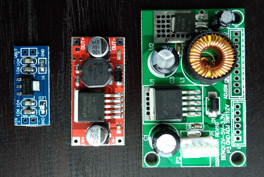
Tiny: ~USD1; *As described by the seller: Input: DC 4.5V--7V (Input Voltage must be Greater than the Output voltage high above 1V.)
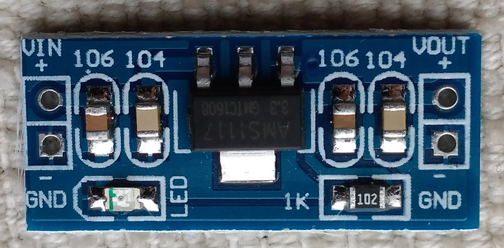
out 3.3V
Boots but keeps restarting.
With a 870 uF at the output:
in 5V: boot time 170-190mA, stable: 170-180mAMid-sized: ~USD1.8; As described by the seller: 10W DC Buck Step Down Regulator Voltage Power Converter Module 3.6v~40v 2A 3.3v
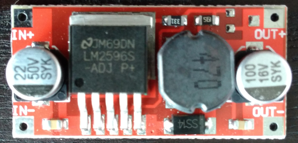 out 3.4V
in 5V: boot time 140-230mA, stable: 165-185mA
in 12V: boot time 40-75mA, stable: 70-75mAThe big one (5V and 3.3V): ~USD2.75; As described by the seller: DC-DC 12V To 5V 3.3V Step-down Power Supply Module, max 3A.
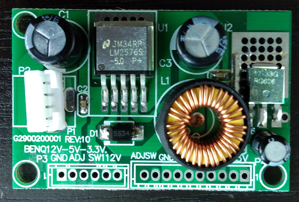
out 3.3V
in 5V: doesn't boot
in 12V: boot time 70-130mA, stable: 100-110mAAnd of course, the advice to add some large capacitors at the output was hitting the nail on the head. The 1117 and its clones make the Omega to boot and work stable with no problems including this 4m poor quality wires. I checked some electrolitic and tantalum capacitors in the range of 800-1000uF.
One more piece of info, I arbitrary limited the current booting with the input of 3.3V, the 2m long 2.3mm conductor and 200-300mA is no go, but 500mA already boots and stays stable (at least for the bare Omega2 used).
Question: is the Vin of 3.4V for the Omages a major concern? I liked the middle-sized converter but this is also the only with the Vout out of range (for both 5V and 12V Vin).
-