Omega 2S+ Ethernet Connection Problem
-
Hello, my name is Akif. I have a new PCB with Omega 2S+ on it. I am trying to connect to internet with Ethernet cable with no success. I had another PCB with Omega 2+ on it it has the same components to the value (except it has another 10uF parallel to 100nF on VCC) with this PCB. I followed "The Ethernet Port" documentation editing firewall file, the old PCB connects to internet with Ethernet bu this one does not.
I will add some attachments below that might help anyone detect the problem, I'm kind of lost here any help is appreciated.
My ethernet port circuitry is below;
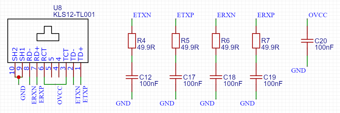
Here's a link to the ethernet connector (it has built in opto circuitry) ;
Ethernet ConnectorHere are some files that might be helpful to solve the problem;
/etc/config/network ;
config interface 'loopback'
        option ifname 'lo'
        option proto 'static'
        option ipaddr '127.0.0.1'
        option netmask '255.0.0.0'

config globals 'globals'
        option ula_prefix 'fd1d:48c4:7633::/48'

config interface 'wlan'
        option type 'bridge'
        option proto 'static'
        option ipaddr '192.168.3.1'
        option netmask '255.255.255.0'
        option ip6assign '60'

config interface 'wan'
        option ifname 'eth0'
        option proto 'dhcp'

config interface 'wwan'
        option ifname 'apcli0'
        option proto 'dhcp'
        option hostname 'Omega-C18A'
/etc/config/dhcp ;
config dnsmasq
        option domainneeded '1'
        option boguspriv '1'
        option filterwin2k '0'
        option localise_queries '1'
        option rebind_protection '1'
        option rebind_localhost '1'
        option local '/lan/'
        option domain 'lan'
        option expandhosts '1'
        option nonegcache '0'
        option authoritative '1'
        option readethers '1'
        option leasefile '/tmp/dhcp.leases'
        option resolvfile '/tmp/resolv.conf.auto'
        option localservice '1'

config dhcp 'wlan'
        option interface 'wlan'
        option start '100'
        option limit '150'
        option leasetime '12h'
        option dhcpv6 'server'
        option ra 'server'

config dhcp 'wwan'
        option interface 'wwan'
        option ignore '1'

config odhcpd 'odhcpd'
        option maindhcp '0'
        option leasefile '/tmp/hosts/odhcpd'
        option leasetrigger '/usr/sbin/odhcpd-update'
/etc/config/firewall ;
config defaults
        option syn_flood '1'
        option input 'ACCEPT'
        option output 'ACCEPT'
        option forward 'REJECT'
        option disable_ipv6 '1'

config zone
        option name 'lan'
        option input 'ACCEPT'
        option output 'ACCEPT'
        option forward 'ACCEPT'
        option network 'wlan'

config zone
        option name 'wan'
        option output 'ACCEPT'
        option forward 'ACCEPT'
        option masq '1'
        option mtu_fix '1'
        list network 'wwan'
        list network 'wan'
        option input 'ACCEPT'

config forwarding
        option src 'lan'
        option dest 'wan'

config rule
        option name 'Allow-DHCP-Renew'
        option src 'wan'
        option proto 'udp'
        option dest_port '68'
        option target 'ACCEPT'
        option family 'ipv4'

config rule
        option name 'Allow-Ping'
        option src 'wan'
        option proto 'icmp'
        option icmp_type 'echo-request'
        option family 'ipv4'
        option target 'ACCEPT'

config rule
        option name 'Allow-IGMP'
        option src 'wan'
        option proto 'igmp'
        option family 'ipv4'
        option target 'ACCEPT'

config rule
        option name 'Allow-DHCPv6'
        option src 'wan'
        option proto 'udp'
        option src_ip 'fc00::/6'
        option dest_ip 'fc00::/6'
        option dest_port '546'
        option family 'ipv6'
        option target 'ACCEPT'

config rule
        option name 'Allow-MLD'
        option src 'wan'
        option proto 'icmp'
        option src_ip 'fe80::/10'
        list icmp_type '130/0'
        list icmp_type '131/0'
        list icmp_type '132/0'
        list icmp_type '143/0'
        option family 'ipv6'
        option target 'ACCEPT'

config rule
        option name 'Allow-ICMPv6-Input'
        option src 'wan'
        option proto 'icmp'
        list icmp_type 'echo-request'
        list icmp_type 'echo-reply'
        list icmp_type 'destination-unreachable'
        list icmp_type 'packet-too-big'
        list icmp_type 'time-exceeded'
        list icmp_type 'bad-header'
        list icmp_type 'unknown-header-type'
        list icmp_type 'router-solicitation'
        list icmp_type 'neighbour-solicitation'
        list icmp_type 'router-advertisement'
        list icmp_type 'neighbour-advertisement'
        option limit '1000/sec'
        option family 'ipv6'
        option target 'ACCEPT'

config rule
        option name 'Allow-ICMPv6-Forward'
        option src 'wan'
        option dest '*'
        option proto 'icmp'
        list icmp_type 'echo-request'
        list icmp_type 'echo-reply'
        list icmp_type 'destination-unreachable'
        list icmp_type 'packet-too-big'
        list icmp_type 'time-exceeded'
        list icmp_type 'bad-header'
        list icmp_type 'unknown-header-type'
        option limit '1000/sec'
        option family 'ipv6'
        option target 'ACCEPT'

config rule
        option name 'Allow-IPSec-ESP'
        option src 'wan'
        option dest 'lan'
        option proto 'esp'
        option target 'ACCEPT'

config rule
        option name 'Allow-ISAKMP'
        option src 'wan'
        option dest 'lan'
        option dest_port '500'
        option proto 'udp'
        option target 'ACCEPT'

config include
        option path '/etc/firewall.user'
-
Here's the output to if config ;
apcli0    Link encap:Ethernet  HWaddr 40:A3:6B:C5:C1:8C
          inet6 addr: fe80::42a3:6bff:fec5:c18c/64 Scope:Link
          UP BROADCAST RUNNING MULTICAST  MTU:1500  Metric:1
          RX packets:0 errors:0 dropped:0 overruns:0 frame:0
          TX packets:0 errors:0 dropped:0 overruns:0 carrier:0
          collisions:0 txqueuelen:1000
          RX bytes:0 (0.0 B)  TX bytes:0 (0.0 B)

br-wlan   Link encap:Ethernet  HWaddr 40:A3:6B:C5:C1:8A
          inet addr:192.168.3.1  Bcast:192.168.3.255  Mask:255.255.255.0
          inet6 addr: fd1d:48c4:7633::1/60 Scope:Global
          inet6 addr: fe80::42a3:6bff:fec5:c18a/64 Scope:Link
          UP BROADCAST RUNNING MULTICAST  MTU:1500  Metric:1
          RX packets:5033 errors:0 dropped:0 overruns:0 frame:0
          TX packets:4309 errors:0 dropped:0 overruns:0 carrier:0
          collisions:0 txqueuelen:1000
          RX bytes:521580 (509.3 KiB)  TX bytes:386418 (377.3 KiB)

eth0      Link encap:Ethernet  HWaddr 40:A3:6B:C5:C1:8B
          inet6 addr: fe80::42a3:6bff:fec5:c18b/64 Scope:Link
          UP BROADCAST RUNNING MULTICAST  MTU:1500  Metric:1
          RX packets:0 errors:0 dropped:0 overruns:0 frame:0
          TX packets:3912 errors:0 dropped:0 overruns:0 carrier:0
          collisions:0 txqueuelen:1000
          RX bytes:0 (0.0 B)  TX bytes:1332992 (1.2 MiB)
          Interrupt:5

lo        Link encap:Local Loopback
          inet addr:127.0.0.1  Mask:255.0.0.0
          inet6 addr: ::1/128 Scope:Host
          UP LOOPBACK RUNNING  MTU:65536  Metric:1
          RX packets:263 errors:0 dropped:0 overruns:0 frame:0
          TX packets:263 errors:0 dropped:0 overruns:0 carrier:0
          collisions:0 txqueuelen:1000
          RX bytes:38842 (37.9 KiB)  TX bytes:38842 (37.9 KiB)

ra0       Link encap:Ethernet  HWaddr 40:A3:6B:C5:C1:8A
          inet6 addr: fe80::42a3:6bff:fec5:c18a/64 Scope:Link
          UP BROADCAST RUNNING MULTICAST  MTU:1500  Metric:1
          RX packets:17704 errors:1906 dropped:0 overruns:0 frame:0
          TX packets:11035 errors:0 dropped:0 overruns:0 carrier:0
          collisions:0 txqueuelen:1000
          RX bytes:2279302 (2.1 MiB)  TX bytes:3218846 (3.0 MiB)
          Interrupt:6
-
You have non zero TX count and 0 RX count?
eth0:
RX packets:0 errors:0 dropped:0 overruns:0 frame:0
TX packets:3912 errors:0 dropped:0 overruns:0 carrier:0From the connector link that you provided, the data sheet shows:
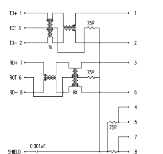 .
.The connections are std 568, ie, 1,2,3,6. Your left most diagram shows 1,2,7,8 .. ? Is physical connection established ?
Or you can try with a one side skinned patch cable of short run:
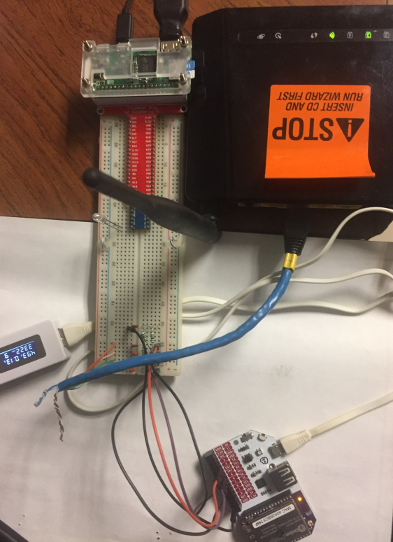
Omega is connected to port3 in the other device, which is a wifi router with 4 ports.
Thanks.
-
@tjoseph1
First of all thank you for your response.I did not quite understand what you meant by with that sentence 1,2,3,6 , 1,2,7,8 stuff.
I checked again just now, the conenctor has 6 pins other than the shield that needs to be connected. I am quite sure my connections are correct. I will add the photos of actual PCB and the design below.I have another PCB with the same design. Only differences are ;
- The old one has an additional 10uF parallel to 100nF on VCC
- Obviously the path are different. Mine are a little longer but I don't think that would be a complete problem.
I use the same cable on the same port of the modem just take it out of the new one and connect it to the old one. The old one can connect but the new one can't.
I did not quite get what you meant by your picture as well (sorry, I'm not well informed on network and such).
I was hoping this would be a software problem but I've checked every related file for both Omegas and they are same.
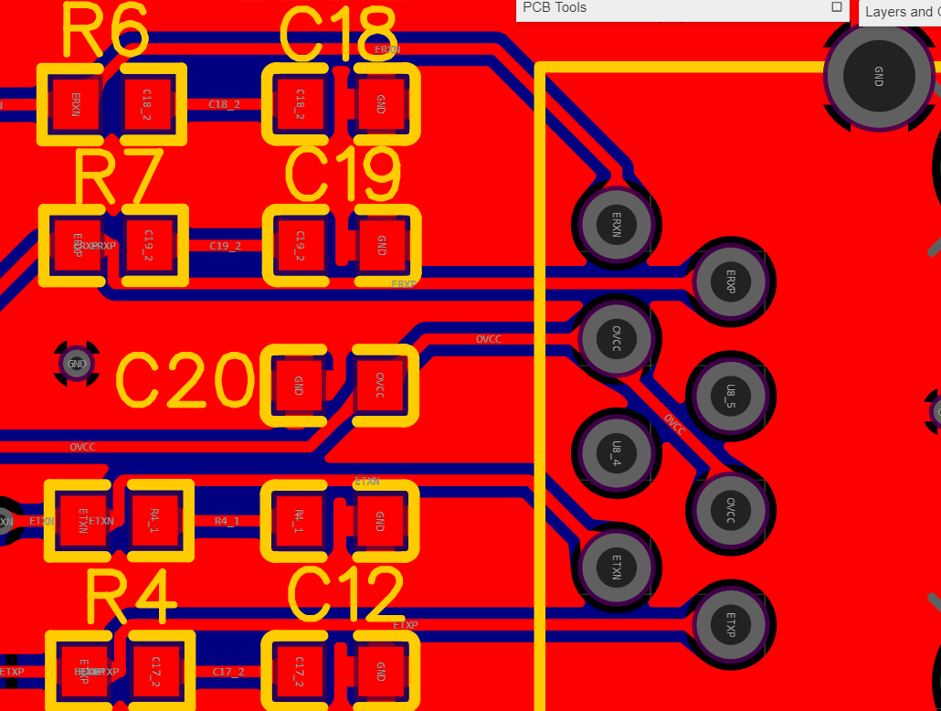
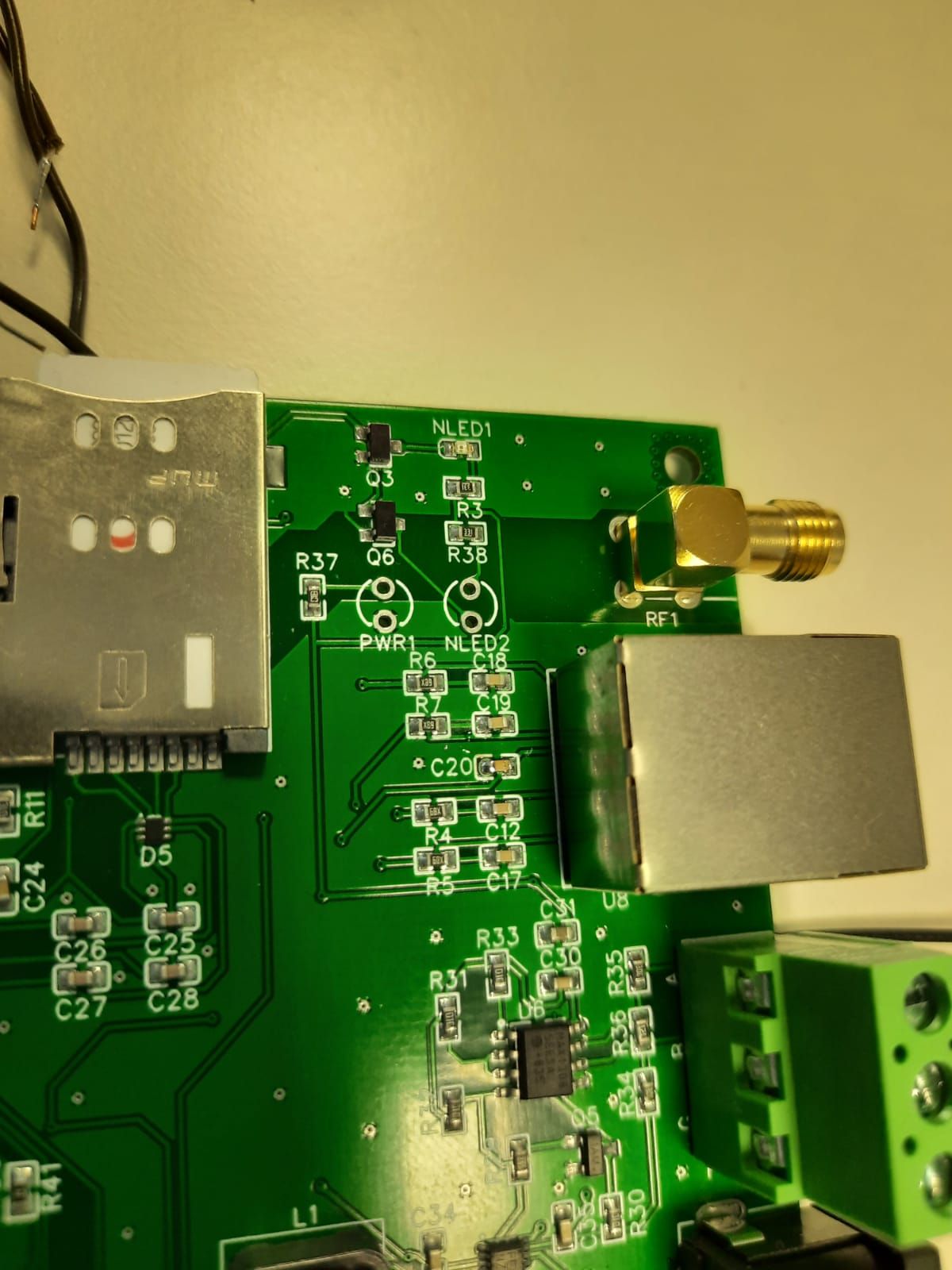
Here's the other side of the PCB two parallel lines are RX+/RX- and TX+/TX-. RX+ and RX- are really close to each other can there be a parallel talk to mess things up?
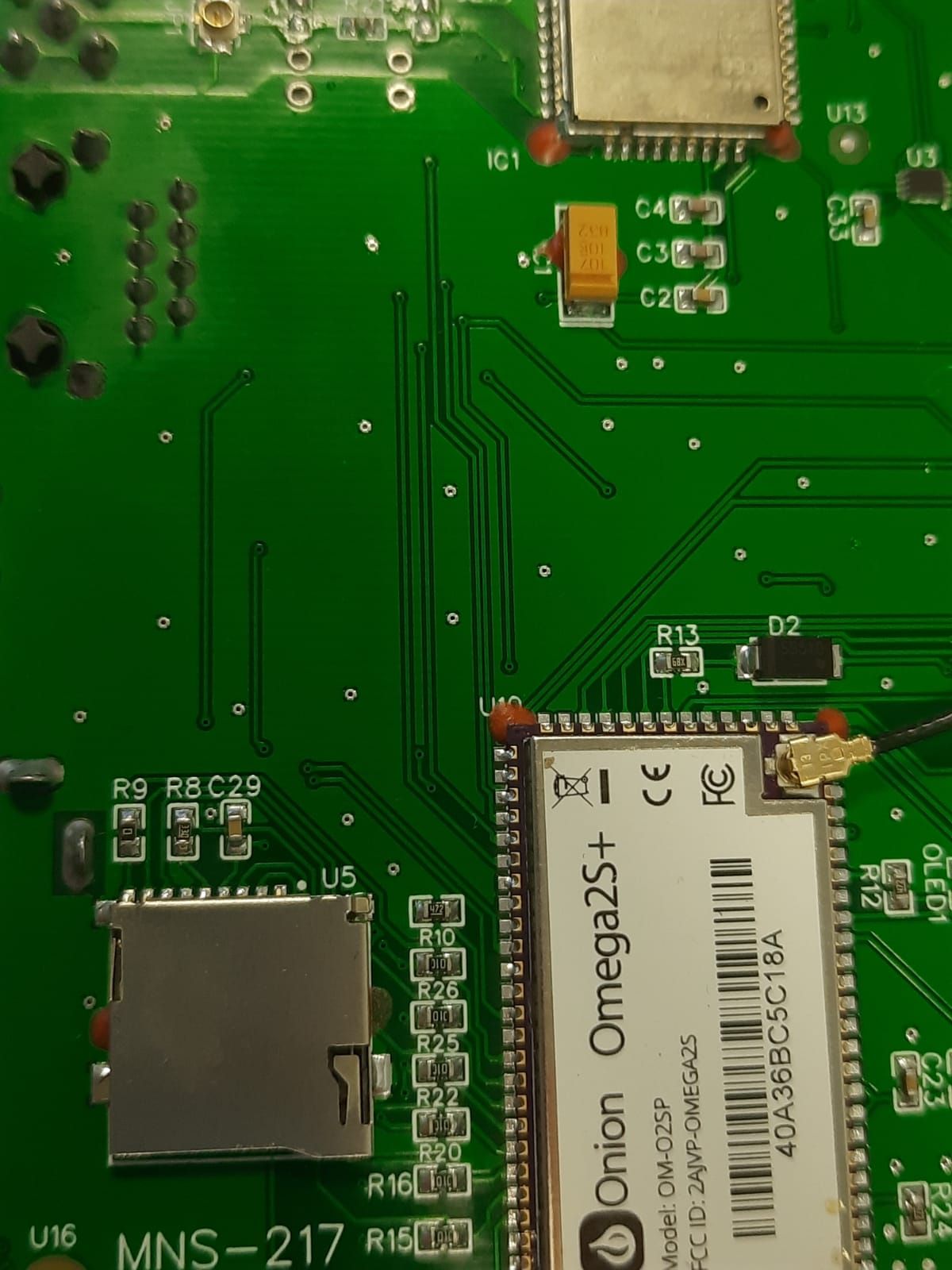
Thank you again.
-
For the UTP Ethernet cabling, 4 wires are used for data (TX+/-, RX+/-). Please see this: https://en.wikipedia.org/wiki/TIA/EIA-568. You can directly jump to the section, "Wiring". The connectivity between two devices' ports uses 4 pins (even though there are 8):
THIS device <=> OTHER device.
1 <=> 3(TX+ <=> RX+)
2 <=> 6(TX- <=> RX-)
3 <=> 1(RX+ <=> TX+)
6 <=> 2(RX- <=> TX-)
pins 4,5,7& 8 are unused (all these numbering are based on the 8 pins that are seen in the Ethernet connector)So, we need to use only pins 1,2,3 & 6 for wiring while making sure that the wire connected to pin1 of THIS device is connecting to the pin3 of the OTHER device.
Most switches have built-in "cross-over". We can forget that for now.
In the first diagram, you showed ERXN as pin 8 and ERXP as pin7. Your EXTXP(pin1) and EXTN(pin2) appear to be correct..
Your eth0 has transmitted packets:3912
The above info can be used to debug the pcb.The photograph I attached follows section "10/100 SMD WAN port", Option 2, from the PDF,
Omega2S-Reference-Schematic.pdf
that is extracted from https://github.com/OnionIoT/Omega2/archive/master.zipUsing that wiring, I was able to connect the omega using TX+/- & RX+/- pins to a switch section of the wifi-router that has 4 ports.
Thanks ..
-
@tjoseph1
Oh ok, I've used that schematic file in my design as well.
I will try to dig into the fact that there is transmission but no response.
Thank you for your contribution.
-
A reliable wired network connection can be a great addition to a project!
-
@akif-durmaz Check out our new Omega2S hardware design guide, there's a section on ethernet design!
https://github.com/OnionIoT/Omega2/blob/master/Documents/Omega2S Hardware Design Guide.pdf
-
@Lazar-Demin
I've designed my PCB according to "Omega2S-Reference-Schematic" file and a PCB which had Omega2+.
Here's the part of Reference Schematic ;
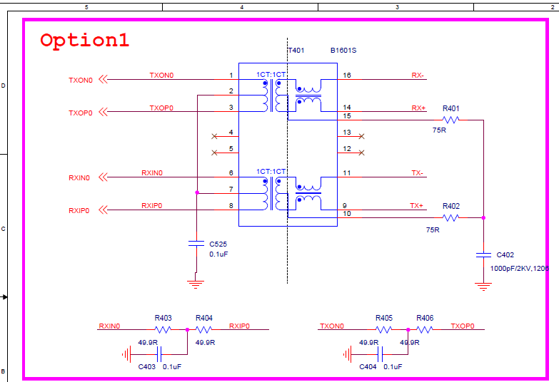
In Reference Schematic RXIN0/RXIP0 and TXON0 and TXOP0 connects together after the resistors and goes through the same capacitor. In my design neither of the signals (RXIN0,RXIP0,TXON0,TXOP0) connects together each goes through their own resistor and capacitor (100nF each). Also pins 2 and 7 are pulled up to 3.3V in my design. Reason for these differences are our other device with Omega2+ has a properly working ethernet connection and it was designed by somebody else like I described. So I wanted to go with the working example in my hand.
The Ethernet Port part in Hardware Design Guide you posted seems to be the cropped version of Reference Schematic and it does not include the resistors part. Can that be a mistake or the whole circuitry should just include 100nF for pins 2-7 now?
I still did not solve my problem. We will design another PCB with Omega2S+ soon before that I would like to detect the source of the problem. Would you suggest that I should make the following adjustment by cutting lines and adding cable connections to see if it works?
- Cut the 3.3V line to the 2-7 make it so they are just connected to the ground through 100nF
- Connect R403-R404 and R405-R406 and use one 100nF for two of them.
After making these adjusments my circuit would be the same as Reference Schematic one.
Thank you for your reply and the Hardware Design link.
-
@akif-durmaz I just followed the reference schema to add ethernet to my PCB based on Omega2S+, I concluded that Onion designers have provided their design so it seems logical that one would follow it. There are lots of wheels, no need to design a new one

-
@crispyoz
My new design is not directly related to ethernet problem, we will change some modules on the card but since there is a problem with ethernet port I wanted to get to the bottom of it before the new card
-
This post is deleted!
-
This post is deleted!
-
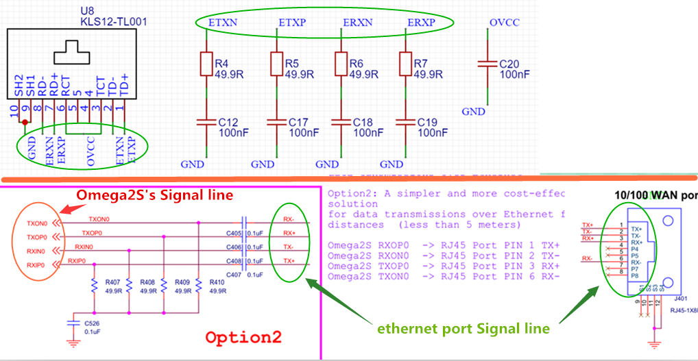
@akif-durmaz Hi ,For the Omega2S reference schematic ,there are two options for the ethernet connection,option1 is using ethernet transformer ,option2 is a simpler circuit which using resistor and capacitor to instead the transformer . and each of the option can work.
I had checked your ethernet port circuitry screenshot, there are some connection is not right, you can't connect the omega2S's ethernet signal line to the ethernet port.
-
The lastest Omega2S reference schematic had deleted the R401~R406,C403 and C404.
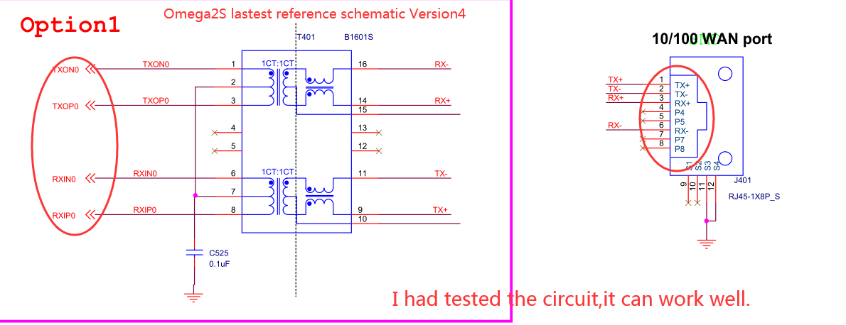
-
@JeffZhou
Hi. I went with Option 1 and used an ethernet connector with a transformer. The following schematic is from the datasheet of my ethernet connector ;
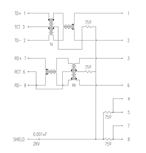
In reference to the picture I think my T+,T-,R+,R- connections are correct. As a secondary confirmation I have a different PCB containing Omega2+ with the same connections and it's ethernet connection has no problem.
If I misunderstood something please correct me, thank you for your reply.
-
@akif-durmaz Hi ,please add a screenshot of the ethernet connector and transformer 's schematic.
-
@JeffZhou
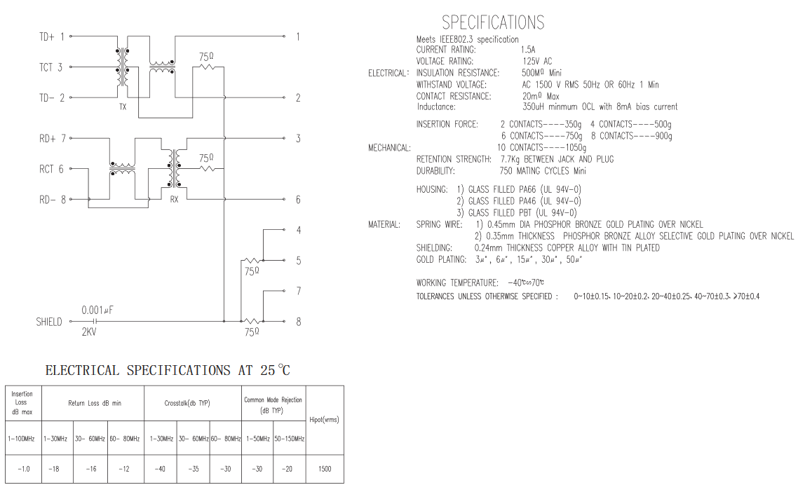
there was a product link in my original post but here, these are the only two pages from the datasheet;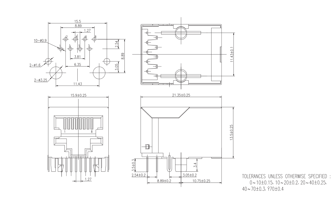
-
@akif-durmaz
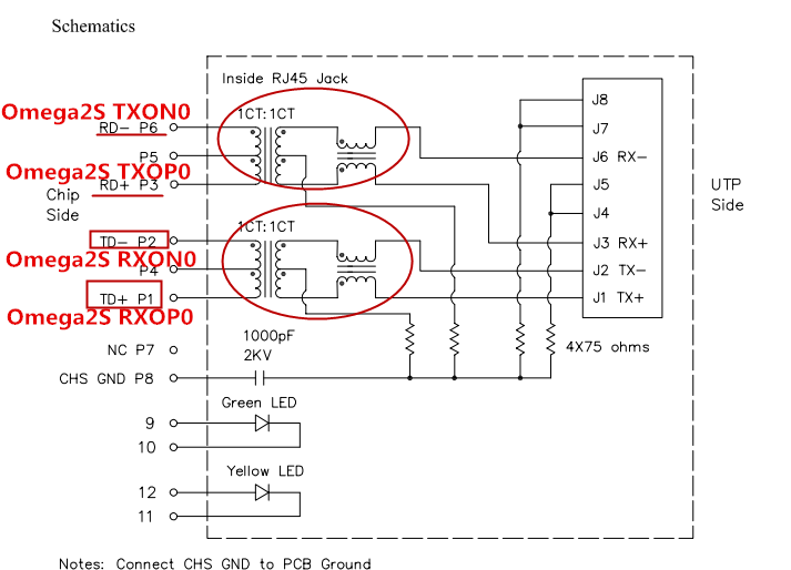
Hi, i had checked the Normal ethernet connector(RJ45),it seems that the inside schematic isn't as the same as yours. Here the connector's sch has the same channel coil of RX/TX.SPEC of HR913550A
-
This post is deleted!