DIY Onion-Mini-Dock
-
@Daniel-Andrade hope it will be available in Brazil too ...
-
Ist the micro usb acts as USB host or client? I think you should add USB host connector...
-
@Victor-Tagayun The schematics show the microUSB-port is simply connected to a CP2102 USB-TTL-adapter. It's not connected to the Omega2 itself.
-
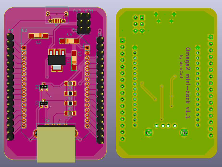
I've never made a single PCB before, let alone used Kicad, but after tussling with it for a day I managed to do my own take on a mini-dock. I skipped on the USB-TTL, because I am going to be using an external one anyways, if needed, nor do I need those reset-buttons, but I did decide to include ESD-protection on the USB-port's data-lines. I also added a header with a couple of extra power-pins, either for powering the device from, or to power any external modules I may want to connect to it.

-
@WereCatf Nice to have another dock option! So, the Omega mounts over the header socket?
-
@Ken-Conrad No, I figured it'd just about fit under the Omega2, when I solder the female 2.0mm headers, but then I just simply forgot to actually measure it.
-
@WereCatf Worth a measure... I'll advise using at least 805 or 12xx SMT resistors and caps as the smaller stuff is the pits to solder!!
-
@Ken-Conrad Aye, they are 0805-size. I have practiced some and I can quite easily solder that size, but smaller than that gets a bit too fiddly for me.
-
@Ken-Conrad I understand P1 is power only. If P1 is a micro USB socket then consider instead a mini USB socket as those are easier to hand solder. Since your board is wired to power external stuff, perhaps a higher current (1.1A) regulator like the AZ1117CR-3.3 is a better choice than the ubiquitous 500ma chips.
-
@WereCatf Does it include USB host connector? Is it breadboard friendly? How many pins still available on each column in the breadboard be, in case it can still fit into breadboard? I think the size still be reduced if you put P1, P2 and 6pin HRD on one side and cut along straight the edge of P3 and P5, this way we can reduce the cost.
Have you tried qoutation from pcb.io? you can manufacture there and use you design so you will get points whenever we order you PCB.
-
I observed P2 might hit the Omega. You can align, P3 and P5 to the first pins of the Omega and cut the PCB along that line. The antenna of the omega will be protruding, but it will be better so it will be fully exposed. Then P1 and P2 and 6pin will be on the other side.
-
@Victor-Tagayun Yes, it does include a USB-host connector; the microB is only for power, the full-size type A is the host-port. And yes, @Ken-Conrad already pointed out that the USB-port would be getting in the way, so I just shuffled the components around. The USB-port would've been in the way of the microSD-slot anyways, which I didn't realize at first, so that's another good reason. Also, no, it's not breadboard-friendly, nor is it even intended to -- it's just not something I have any need for.
-
@WereCatf If not for breadboard, so it means it will be on some kind of proto board?
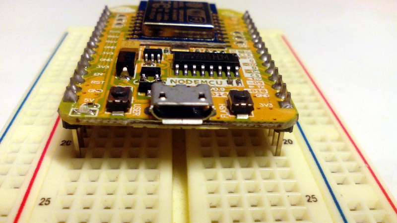
NodeMCU V1 as shown was first not breadboard friendly at first..


The work around they did were like...


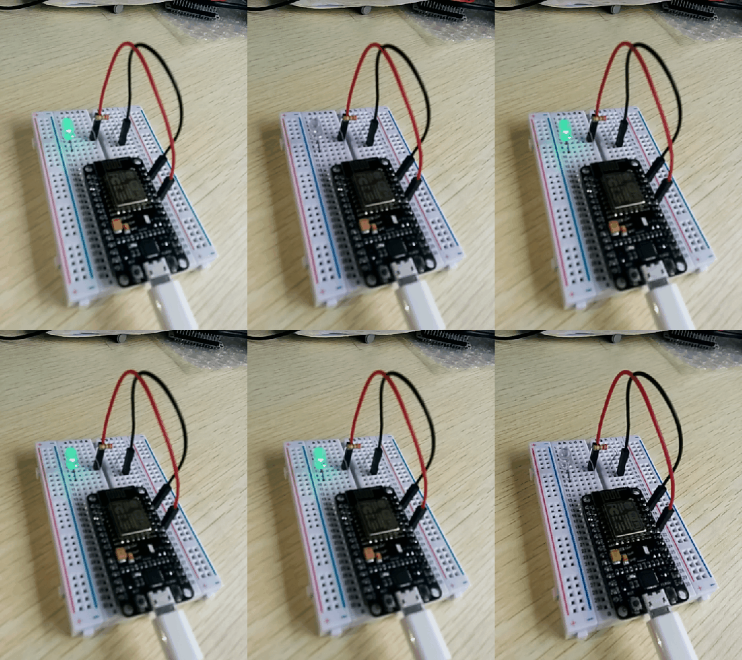
Then due to market demands they make V3 smaller to fit the breadboard...


I hope you will consider being breadboard frieldly even using 2pcs of breadboard.
-
@Victor-Tagayun WereCatf designed his board to use wires with female connectors on the headers. Since he used 2.54mm pin header his dock design can be used a breadboard - you would just solder the pins facing down on the board's bottom. Use two small breadboards and it would work fine.
Here is another dock/ shield design to consider, on his github page he has another shield designed for breadboards.
-
@Ken-Conrad Thank you for the information. The other PCB doesnt have USH host connector, not suitable for me.
@WereCatf How to order this PCB by the way?
-
Well, I published the whole KiCad-project, including gerbers, a picture of the board, schematics as a PDF and all at https://github.com/WereCatf/Omega2-mini-dock -- the project is at V1.2 at the moment, released as public domain.
It's still entirely possible I have more mistakes in there, but maybe @Ken-Conrad or one of the other more-experienced people will give a quick look-over and voice their approval/disapproval. This said, I designed it for my own needs and I am pretty satisfied with it now, think it's time to start thinking about ordering the PCBs done.
-
hello I dont think the width of the Omega itself will fit breadboard plus the 2.54mm pitch headers. So it is not possible to be breadboard friendly anyway, except for the breadboard dock (expensive) which makes the board longer.
Now will wait for your PCB...
-
One approach could be to put the 100-mil pins inside the 2mm ones.
But if your goal is something breadboardable, you may be better off with a Linkit Smart anyway
-
@Chris-Stratton Tbh, the Omega2 itself is already too wide for breadboard-use, even without a dock and even if it did use 2.54mm headers -- there wouldn't be enough room on either side of it to connect anything. As such the dock doesn't really change anything in that regards.
-
The omega2 is only a tiny faction of a row wider than a Linkit Smart, which leaves a row clear on each side when its 100-mil headers are inserted into a breadboard. Putting the 100-mil headers inside the 2mm ones could potentially even allow a second row accessible under the overhang (module could be unplugged by wiring).
But that's a "just saying" - if I personally wanted to breadboard something, I'd use the Linkit Smart, while in actuality I'm working with a slightly narrower surface mount module on custom application PCBs.