CAN Bus: using MCP2515 with Omega2
-
I built a board with Omega2S+ and MCP2515.
MCP2515 is connected to the SPI bus.
CS1 and GPIO11 is used for CS# and INT# pins.Here's the device tree modification I made in
target/linux/ramips/dts/mt7628an_onion_omega2.dtsifile.&spi0 { status = "okay"; pinctrl-names = "default"; pinctrl-0 = <&spi_pins>, <&spi_cs1_pins>; flash0: flash@0 { ... }; can0: can@1 { compatible = "microchip,mcp2515"; reg = <1>; spi-max-frequency = <5000000>; clock-frequency = <20000000>; interrupt-parent = <&gpio>; interrupts = <11 IRQ_TYPE_EDGE_FALLING>; }; };I choose
kmod-can-mcp251xin configuration.
After guilding and flashing, I could check the MCP2515 initialization success bydmesg.The
cansendcommand worked, and I could see the correct CAN bus signal is outputting from MCP2515.
But when I triedcandumpto get packets from external sensor modules, it didn't work.Did anyone successfully used MCP2515 in this way?
-
-
@crispyoz I've checked all these threads before.
They were using bitbanged version, modified MCP251x driver.
Can't it be done with non-bitbanged driver of GBert?
-
@DumTux Alas not my area of expertise. However if my project require robust full duplex, I'd use something that supported it. duck from flames
-
@crispyoz
Indeed. I totally agree with you.
Unfortunately, I am now working on the existing project.
Moving to some other platform will require a lot of work of porting existing software, that are already developed for Omega2.
-
@DumTux I think @luz and @Lazar-Demin have expertise in this area so tagging them here.
-
For the Kernel update from 5.4 -> 5.5, the MCP251x driver has updated to support half-duplex SPI masters.
It automatically detects the SPI mode whether it is full or half duplex like this.if (spi->controller->flags & SPI_CONTROLLER_HALF_DUPLEX) {I am now working with OpenWrt 22.03, which has Kernel 5.10 version.
Thus it should work out of the box. At least, I expected so.
But it seems like still IRQ problem is in my device tree setting.
-
@DumTux Two avenues to pursue here:
1) SPI issue
The Omega2 family does not support full-duplex SPI transmissions because of a hardware bug in the underlying MT7688 SoC used in the Omega2. More details in this FAQ post.
The MT7688 is intended to support full-duplex, so it will have all of the full-duplex flags. I'm not sure how that will impact your driver.
An alternative would be to setup software based SPI and instantiate your mcp2515 driver on the software SPI. We have information on how to setup a sw SPI bus from userspace, but we don't have experience with sw SPI using the DTS file.2) IRQ GPIO in DTS
If I'm reading the DTS file correctly, these lines mean that GPIO11 being is used for the interrupt line?
		interrupt-parent = <&gpio>;
		interrupts = <11 IRQ_TYPE_EDGE_FALLING>;
Using GPIO11 might be causing the issue. From our GPIO documentation article:
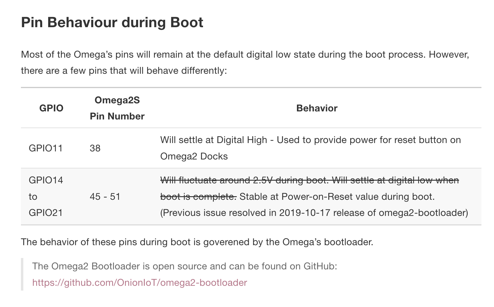
Is there any way you can use a different GPIO for the interrupt line? Even if it's temporary, just to confirm this is causing the issue.
Any GPIO not listed as a special pin will do fine.
-
@Lazar-Demin
Thank you for thorough reply.1) SPI issue
If so - MT7688 is designed for full-duplex but working as half-duplex by design bug, it may not have
SPI_CONTROLLER_HALF_DUPLEXflag. Thus thekmod-can-mcp251xmay go into full duplex mode.I will try to insert
printkstatements to see the half-duplex mode activation viadmesgI cannot use software SPI, as it requires the MCP2515 wired to GPIO pins, instead of hardware SPI pins.
I designed my board with Omega2S+, build PCBA prototyping using PCBCrew prototyping service.
So it's not so simple to change wiring at the moment.2) IRQ GPIO in DTS
Yes, GPIO11 is used for interrupt pin. The reason I used it is like this. There was old project based on OpenWrt 18.06. The old hardware used GPIO11 for interrupt pin. We lost connection with the old developer team.
The old developers patched the MCP251x driver of Kernel 4.14 for half-duplex support.
At the time of their working, half-duplex MCP251x driver was not yet there in Linux mainline.
However, since Linux kernel upgrade 5.5+, MCP251x driver changed a certain amount.
I tried to use the old patched version of driver, but it was written for Kernel 4.14 and not compatible with current 5.10 of OpenWrt 22.03.The old DTS has the following GPIO configuration. It might be related the issue you mentioned.
		canInt {
			label = "canInt";
			gpios = <&gpio 11 GPIO_ACTIVE_LOW>;
		};
By the way, I am using OpenWrt 22.03 custom build.
Does my built image is boot by Omega2's bootloader?
I thoughtu-bootis managing boot sequence in custom built image.
-
Current hardware schematics is here.
https://github.com/dumtux/omega2-4g-gateway/blob/develop/doc/schematics-v3.0a2.pdf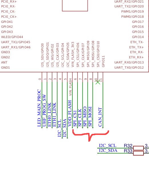
The following picture shows the board in action.
The module in my hand is an angle sensor, that is emitting CAN messages.
I checked it's working correctly with oscilloscope.
I am trying to get the CAN packet withcandumpcommand.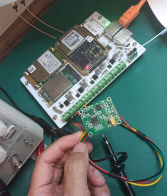
I could see the
can0is present byipconfig, and I could up the link, send packets bycansendcommand.
What I am stuck is thatcandumpis not working. As there is IRQ issue.root@OpenWrt:~# dmesg | grep -i mcp251x [ 395.392687] mcp251x spi0.1 can0: MCP2515 successfully initialized. root@OpenWrt:~# ip l | grep -i can 6: can0: <NOARP,ECHO> mtu 16 qdisc noop state DOWN mode DEFAULT group default qlen 10 link/can root@OpenWrt:~# ip link set can0 up type can bitrate 125000 root@OpenWrt:~# candump can0 (nothing happens from here ...)
-
@Lazar-Demin and @crispyoz
I added the following debug lines intomcp251x.cto check if it's going into half-duplex mode correctly.... printk("MCP251x-MT7688 : spi->controller->flags : %d", spi->controller->flags); printk("MCP251x-MT7688 : SPI_CONTROLLER_HALF_DUPLEX : %ld", SPI_CONTROLLER_HALF_DUPLEX); if (spi->controller->flags & SPI_CONTROLLER_HALF_DUPLEX) { printk("MCP251x-MT7688 : set as half-duplex mode"); ...And made it as a temporal
mcp251x-mt7688module and installed it after compilation.
Here'sdmesgresult.root@OpenWrt:~# dmesg | grep -i mt7688 [ 0.000000] SoC Type: MediaTek MT7688 ver:1 eco:2 [ 52.310755] MCP251x-MT7688 : spi->controller->flags : 1 [ 52.310769] MCP251x-MT7688 : SPI_CONTROLLER_HALF_DUPLEX : 1 [ 52.325683] MCP251x-MT7688 : set as half-duplex mode [ 52.331336] MCP251x-MT7688 : spi->controller->flags : 1 [ 52.336382] MCP251x-MT7688 : SPI_CONTROLLER_HALF_DUPLEX : 1 [ 52.355689] MCP251x-MT7688 : set as half-duplex mode root@OpenWrt:~#As we can see, the MCP251x driver works as half-duplex mode on MT7688 CPU.
Thus my problem certainly related to the IRQ only.
Still need your helps.
-
2) IRQ GPIO in DTS
After confirming that the MCP251x driver is initialized as half-duplex mode as desired, I came back to investigate IRQ issue.
I measured the GPIO11 with an oscilloscope. The result was exactly like you mentioned.
BPIO11 was always HIGH and never tirggered even though there are incoming packets.Is there a quick way to check if GPIO11 is released from Omega2's bootloader for general-purpose use?
In other word, how can I check the IRQ is properly configured on GPIO11?
-
@DumTux said in CAN Bus: using MCP2515 with Omega2:
Is there a quick way to check if GPIO11 is released from Omega2's bootloader for general-purpose use?
If you can "export" it via the '/sys/class/gpio' interface (before loading your driver that may try to use it, and possibly block it even if not successful establishing it as IRQ), then it should be available.
However, when you are using unpatched 22.03, the
/sys/class/gpiointerface (deprecated by now) will have completely strange GPIO numbering: GPIO 0..31 -> 480..511, GPIO 32..63 = 448..479.
So you'd need to export GPIO 491 to get GPIO 11.I am using a patch on top of 22.03 to bring back the
gpio-baseDT property which allows to revert the numbering back to what it was in 19.07. New projects should use the new gpiod interface, but this is not entirely ready yet, see my attempt to find out what the status of GPIOs in OpenWrt is.
-
This post is deleted!
-
@DumTux said in CAN Bus: using MCP2515 with Omega2:
Fabulous!
After a few seconds of power on, GPIO11 went to HIGH status and never dropped to LOW level while MCP2515 operating. Instead, after CAN bus enabling, the GPIO11 voltage was ~2.0V.
I think it was because MCP2515 was trying to pull down, while Omega2 is trying to output HIGH.But with that GPIO number fixing, it dropped to LOW after CAN bus enabling.
Here's the results.root@OpenWrt:~# ls /sys/class/gpio/ export gpiochip416 gpiochip448 gpiochip480 unexport root@OpenWrt:~# echo 491 > /sys/class/gpio/export root@OpenWrt:~# ls /sys/class/gpio/ export gpio491 gpiochip416 gpiochip448 gpiochip480 unexport root@OpenWrt:~# cat /sys/class/gpio/gpio491/direction out root@OpenWrt:~# echo in > /sys/class/gpio/gpio491/direction root@OpenWrt:~# cat /sys/class/gpio/gpio491/direction in root@OpenWrt:~# insmod /lib/modules/5.10.146/mcp251x.ko root@OpenWrt:~# ip l | grep can 6: can0: <NOARP,ECHOmtu 16 qdisc noop state DOWN mode DEFAULT group default qlen 10 link/can root@OpenWrt:~# ip link set can0 up type can bitrate 125000 root@OpenWrt:~#Just after this
ip link set can0 upcommand ran, the GPIO11 dropped to LOW.
I think MCP2515 is pulling down the INT# pin as it is constantly receiving packets from external sensor.I'll keep my further working results posted.
-
@luz @Lazar-Demin @crispyoz and all!
I am still having trouble with CAN bus driving.Current behavior
- I set GPIO11 as input and load the MCP251x kernel module as per above discussion.
- Now enable
can0and send packets using these commands.
root@OpenWrt:~# ip link set can0 up type can bitrate 125000
root@OpenWrt:~# cansend can0 01a#11223344AABBCCDD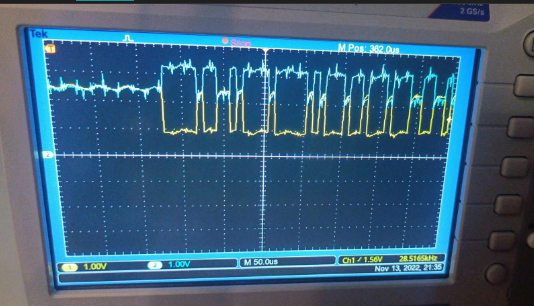
- I can see the waveform on bus by oscilloscope correctly.
- Restart the bus as loopback mode to test somthing different.
root@OpenWrt:~# ip link set can0 down root@OpenWrt:~# ip link set can0 up type can bitrate 125000 loopback on- Now the INT# (GPIO11) falls to LOW. MCP2515 stopped working.
*** MCP2515 does not recover even though I disable/enable the bus again like this.
root@OpenWrt:~# ip link set can0 down root@OpenWrt:~# ip link set can0 up type can bitrate 125000- I have to turn off the board power and turn it on again to make MCP2515 INT# recovered.
dmesgshows nothing except success logs like this during all these operation.
... [ 68.586340] mcp251x spi0.1 can0: MCP2515 successfully initialized. [ 69.759118] IPv6: ADDRCONF(NETDEV_CHANGE): can0: link becomes ready [ 124.360819] IPv6: ADDRCONF(NETDEV_CHANGE): can0: link becomes ready ...- The same situation goes for when I connect external sensor module, that emits CAN message periodically.
- As soon as any external packet is coming in, the MCP2515 INT# falls to LOW. I can read nothing via
candump. - All this behavior were the same no matter of setting GPIO11 as IN or not before loading the MCP251x kernel module.
Questions
- Is this still IRQ problem?
- Is there any way to check MCP2515 resistor values using
canutilspackage commands? - Is there other reading method except
candump? For example, instead of inturrupt-basedcandump, manual polling.
-
I am going to try to modify the bootloader to not handle GPIO11 for the dock power supply.
There is a bootloader on OnionIoT GitHub account, but it seems like outdated.
And I could not find the current OpenWrt 22.03 build using it.Thus, I guess GPIO11 handling is somewhere patched inside OpenWrt 22.03's specific config files.
I could see some MediaTek related config patches underopenwrt/package/boot/uboot-mediatek/.
There I either cannot find specific configs related to Omega2.
As MT76x8 is used in router products a lot, I don't believe the Omega2 specific config will be under this location.Where can I find the OpenWrt 22.03 bootloader for Omega2?
-
@DumTux The bootloader is independent of the firmware. If you've reflashed your Omega2, it will still be running the factory bootloader.
The factory bootloader is compiled from this source code: https://github.com/OnionIoT/omega2-bootloader/
GPIO11 is set high to be compatible with the reset button on the Omega2 Docks. You can find that here in the bootloader: https://github.com/OnionIoT/omega2-bootloader/blob/master/lib_mips/board.c#L3028When you've compiled your own bootloader, follow these instructions to update your device: http://docs.onion.io/omega2-docs/Web-Recovery-flash-bootloader.html
-
void gpio_init(void)
{
  ....
  RALINK_REG(RT2880_REG_PIODIR+0x04)=val;

  /*
  //zh@onion.io
  //setting GPIO 11 High, required for the reset button to work
  val=RALINK_REG(RT2880_REG_PIODIR);
  val|=1<<11;
  RALINK_REG(RT2880_REG_PIODIR) = val; // GPIO 11 direction output
  val=RALINK_REG(RT2880_REG_PIODATA);
  val|=1<<11;
  RALINK_REG(RT2880_REG_PIODATA) = val; // GPIO 11 High
  */

  //jeffzhou@onion.io
  //adding for read wifi MAC address.
  unsigned char macbuf[6];
	raspi_read(macbuf, CFG_FACTORY_ADDR - CFG_FLASH_BASE + 0x04, 6);
	printf("wifi mac address = %02X%02X%02X%02X%02X%02X.\n",
      macbuf[0],macbuf[1],macbuf[2],macbuf[3],macbuf[4],macbuf[5]);
}
I commented the GPIO11 related part in the bootloader source code, and built it.
Just usedmakecommand.After entering to Web recovery mode on Omega2's boot, I went to uBoot upgrade page.
There was Very dangerous warning, but I proceeded.
And after done, that dangerous result happened - not booting.
Is there some
makeoption to build a bootloader specfic for Omega2+ ?
-
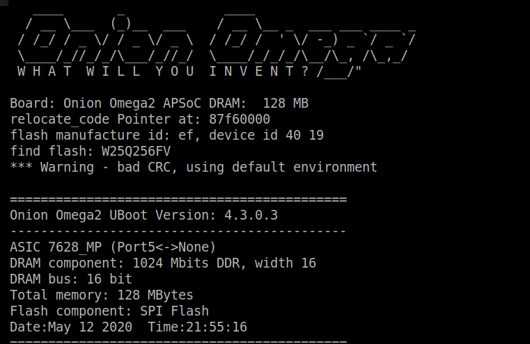
As a comparison, this is normal booting screenshot from the factory bootloader.
It is showing DRAM size 128MB, while my above wrong bootloader shows as 64MB.
Also, flash memory is wrongly recognized.