gps receiver not locking
-
@Ian-Marchant said in gps receiver not locking:
From this photo however, I am not 100% sure which part i am supposed to use?
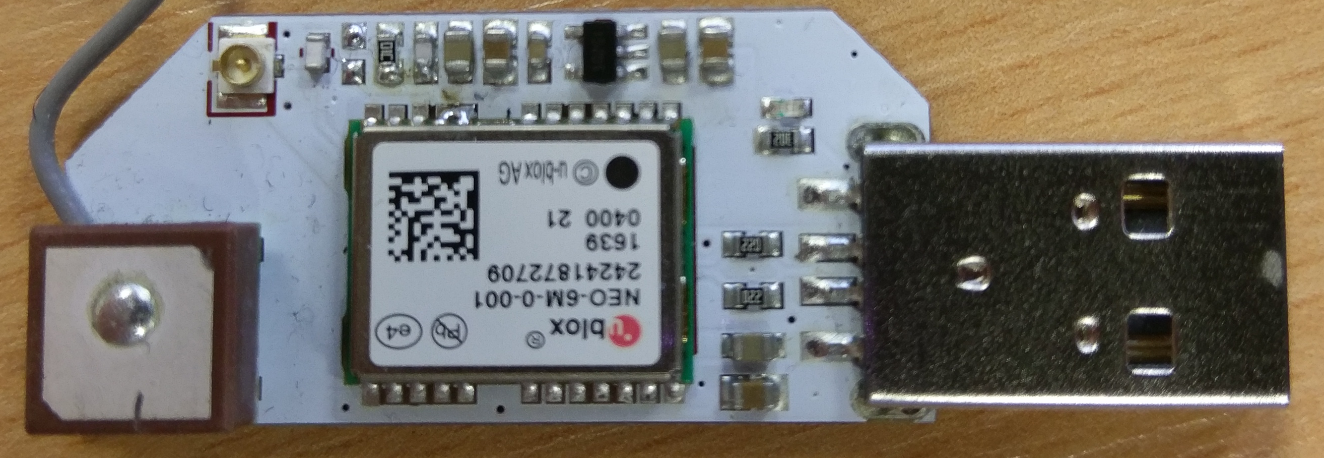
If that is a picture of your receiver then it's time for an RMA following the comments from Chris Stratton. Or did Onion send you the photo?
-
Hi,
That is a picture of my board as it arrived from Onion. I have not made any modification at all.
The only thing I have done to it is to disconnect the antenna and connect an external active antenna. Once the external antenna is connected I get a solid fix with no issues. With the internal antenna... nothing.
Cheers.
-
So you are unable to carry out the remedial work requested by Onion as the rogue capacitor doesn't appear to be there. I would send it back as faulty.
-
Working with an external antenna would not be inconsistent with my suspicions, but those are formed from only a few minutes looking at your picture and a schematic of a different board.
Anyway, it looks like the suggested rework is already applied, so no use for your soldering iron right now. If you do want to poke at it with tools, you could consider with the system unpowered measuring the resistance between the bridged pair of pins on the module and each side of the white ceramic chip inductor beside the antenna. That is not guaranteeed to be 100% safe for all circuit but is usually tolerated, and could help show if there's an issue with the antenna bias supply.
I have to stress though that this is all guesses.
-
Hello,
I have the same issue: unable to lock onto a satellite, indoors and outdoors
 . If it's a hardware problem like I understand it in previous posts, I hope there will be a replacement...
-
i got an reply that they aren't going to replace the GPS dock and requires us the customer to unsolder the capacitor saying that "It's not their fault"
I'm very angry with this situation. anyone else got the same reply and feeling the same ?

-
@dennis-ctp Mine doesnt even have the capicitor and still very very crappy reception if at all both inside and outside..
-
Anybody managed to get the GPS Expansion working?
-
I also have a board like the image @Costas-Costas posted and while i get GPS data via COM port without the VCP Sensor Drivers.. It does not fix location.
Per this thread I installed the U-Block u-center app and installed the VCP drivers and using their console and app I still am unable to get location and fix.
sigh
-
i attached a small indoor antenna, about 3 times the size of the factory one and am able to get a fix which i was not able to do with the factory setup. if the explanation of onion is to be accepted it seems the cap in question dampens the signal to the unit and thus either a better antenna to increase signal or removing the cap to increase signal. the unit pretty much pinpoints exactly where it is, per my experience, once it gets adequate signal.
edit: i wanted to mention that the antenna i'm using in replacing the factory unit is one off this gps shield board i got a while back. https://www.makerfabs.com/index.php?route=product/product&product_id=133&search=gps+shield
i think you can pick up one like this for ~$3.
-
My GPS receiver won't lock with the built-in antenna; I connected it to my Pixel phone USB port, started up Droid Term, and immediately saw the NMEA strings - good. However, no fix, just a lot of commas. So then I plugged in my external antenna/LNA and almost immediately got a fix. My board has a blank component location in the second spot from the U.FL connector - if I understand correctly, this is where the capacitor that needs to be removed was and is thus already removed.
Certainly not useful without a remote antenna - makes me think the built-in antenna is not functioning correctly.
-
Based on what I read here I have an 'updated' unit without the capacitor in location and still not getting a fix on position in any regard.
Also read that Onion is not taking nor readying replacements admitting the issue yet not taking responsibility.
Should I just trash this into the failed hardware bin for now or any hope of a response from Onion on this thread and/or placing a ticket?
Frustrated..
-
@Dana-Myers114 I may have had a breakthrough with the GPS sensitivity issue. In the course of tinkering with my GPS receivers (removing the antennas, inspecting them, etc.) I found that sensitivity appears to be restored if you re-route the coax pigtail from the antenna so that it's not over the PCB:
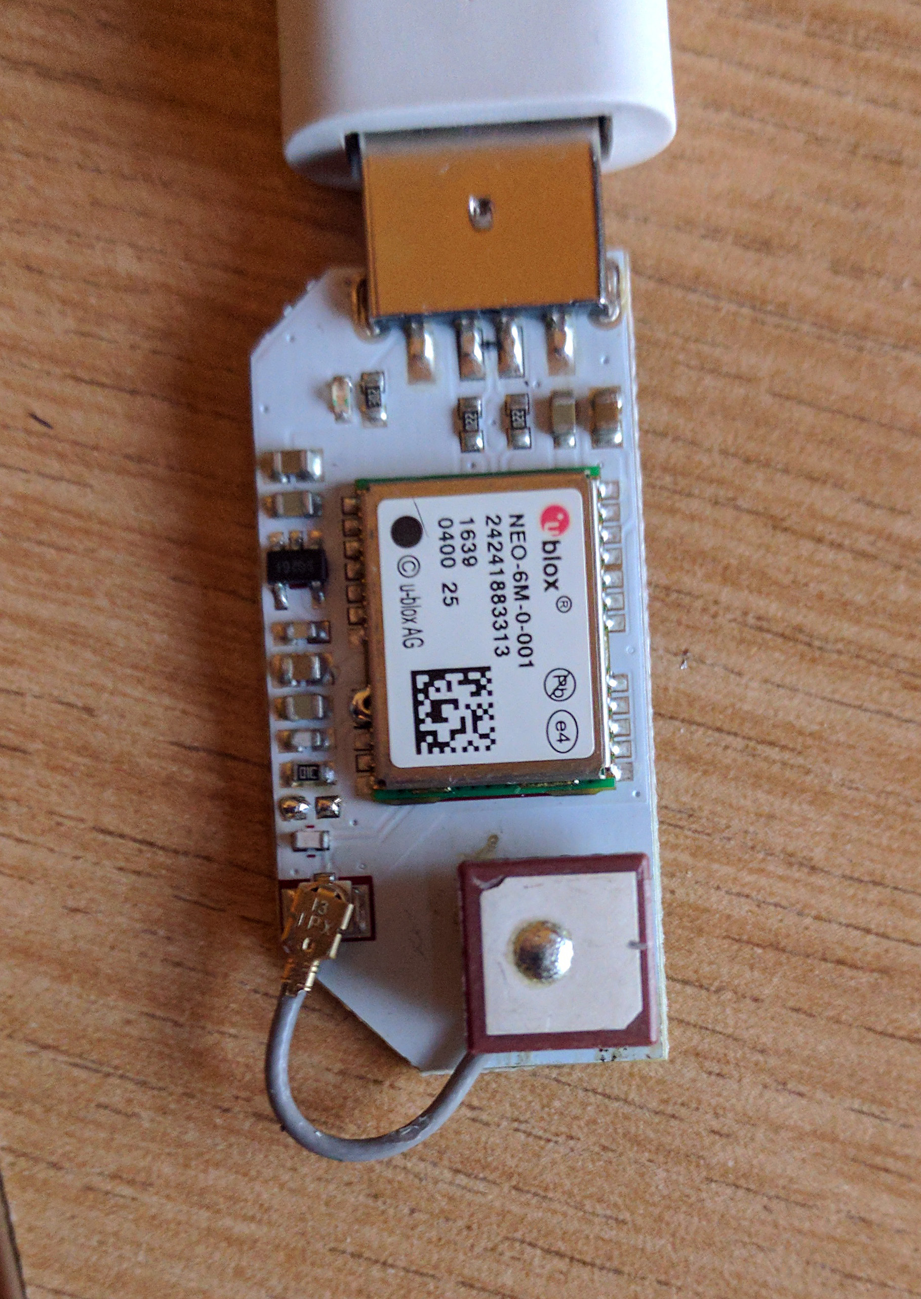
This appears to reliably fix every one of my 3 GPS EXPs. I did desolder/resolver the antenna in each case before discovering this, but I don't think that's necessary - I think you may be able to fix your GPS by removing the pigtail from the U.FL connector on the PCB, re-route it, and replace it on the U.FL.
If you can try this and report back, I'm curious to hear how it works for you.
(I think this has to do with the cable/connector being too close to the input component on the PCB but that's speculation).
Dana
-
Dana, i tried that first thing after disconnecting the cable thinking that it might be a poor connection from the factory and having the pigtail like your picture did not help my situation. however your remark about doing a repair to the connector solder joints makes me think that once i get my other omega2+ in the mail later this month that i will give that a try as there could just be a problem with the soldered connection. for now, having a larger antenna solves the signal issue for me but creates an issue of not having a good place for the larger antenna.
-
@Douglas-Kryder the other thing I did that may be notable, after desoldering the antenna from the PCB, is clearing excess solder from the antenna left over from when it was originally soldered to the PCB. In particular, one corner of the LNA shield (on the bottom of the antenna) is cut-away, but when it was soldered to the PCB, this corner was filled with solder and shorted to a pad/via on the LNA board. I cleared that on all of my 3 GPS Exps as part of the R&R and did not re-fill it when re-mounting the antenna. Given the shield is cut-away there, I believe it's not meant to short to the pad and this may be deafening the LNA.
-
Nice! Something to test and hoping it works for some but for me, at least, it seems it's still not locking properly in the u-Center app as well others.
I have a new antenna coming in that has some distance in hopes that will resolve the issue within days. I did try your re-route of the connector wire but alas; it didn't lock. What it did do, however, is seem to increase the signals that I do get compared to them when the connector wire is across the board, lol.. Getting there
")
-
@Dana-Myers114 Thanks for the tip, desoldering and re-soldering did the trick, mine also had a solder blob where shouldn't be. It's now working fine.
-
@Dana-Myers114 said in gps receiver not locking:
@Douglas-Kryder the other thing I did that may be notable, after desoldering the antenna from the PCB, is clearing excess solder from the antenna left over from when it was originally soldered to the PCB. In particular, one corner of the LNA shield (on the bottom of the antenna) is cut-away, but when it was soldered to the PCB, this corner was filled with solder and shorted to a pad/via on the LNA board. I cleared that on all of my 3 GPS Exps as part of the R&R and did not re-fill it when re-mounting the antenna. Given the shield is cut-away there, I believe it's not meant to short to the pad and this may be deafening the LNA.
thank you. i'll look for that on mine when i do the de-solder/solder work.
-
@Endre-Czirbesz said in gps receiver not locking:
@Dana-Myers114 Thanks for the tip, desoldering and re-soldering did the trick, mine also had a solder blob where shouldn't be. It's now working fine.
That's 2 now, with an desolder and re-solder, seemingly working well so I think I'll try mine soon. Just visually the antenna on mine is crooked and seems 'blobbed' as well so hoping once I get the chance, I'll see if mine also helps.
Thank you all!
-
Does anyone have a photo or better description of where the blob is?