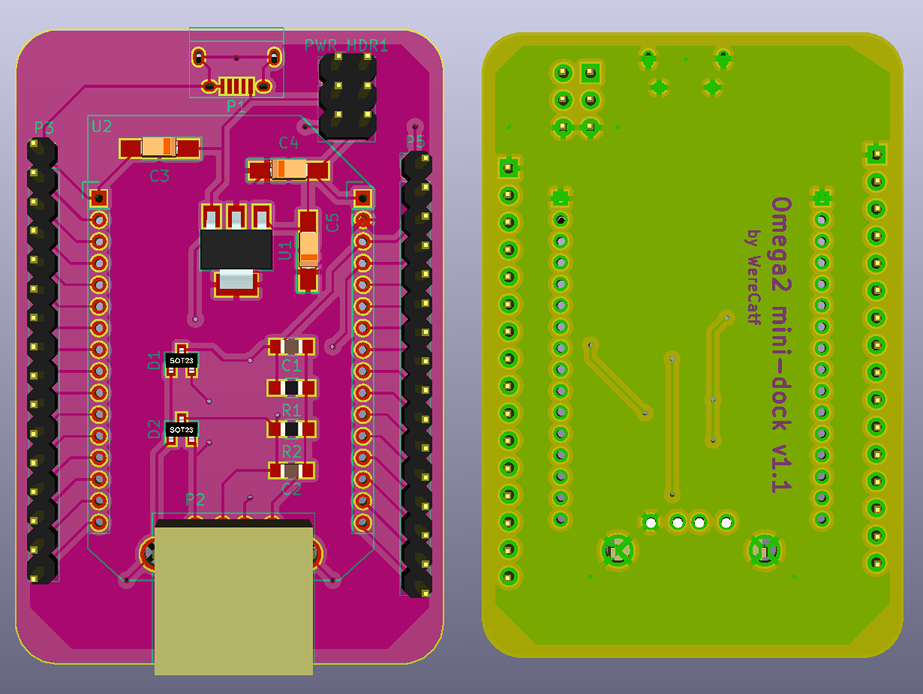
DIY Onion-Mini-Dock
-
@Daniel-Andrade It's an excellent idea to have the Omega pins available for customized use, and on standard headers to boot.

-
@fossette Yes, I want it to be Breadboard friendly!
-
@Daniel-Andrade Cool. So basically a form of Mini dock with all the pins exposed for breadboarding/external connections. Great

-
This is great! I thought of doing something like this myself, but yours is much more capable. I want one!
-
Just sent the first board to production.
Going to CES and taking some holidays. I will be back in mid-january.If everything works I will post here and I can send them to anyone with production + shipping cost

-
@Daniel-Andrade Please do. I'd be interested!
-
Also see https://community.onion.io/topic/1338/new-omega2-basic-shield-power-ftdi-i2c-and-spi for something very similar
-
@Daniel-Andrade any news on your boards?
-
@Costas-Costas @Daniel-Andrade I too would be most interested in any updates on availability of this. Thanks
-
@Daniel-Andrade hope it will be available in Brazil too ...
-
Ist the micro usb acts as USB host or client? I think you should add USB host connector...
-
@Victor-Tagayun The schematics show the microUSB-port is simply connected to a CP2102 USB-TTL-adapter. It's not connected to the Omega2 itself.
-
I've never made a single PCB before, let alone used Kicad, but after tussling with it for a day I managed to do my own take on a mini-dock. I skipped on the USB-TTL, because I am going to be using an external one anyways, if needed, nor do I need those reset-buttons, but I did decide to include ESD-protection on the USB-port's data-lines. I also added a header with a couple of extra power-pins, either for powering the device from, or to power any external modules I may want to connect to it.

-
@WereCatf Nice to have another dock option! So, the Omega mounts over the header socket?
-
@Ken-Conrad No, I figured it'd just about fit under the Omega2, when I solder the female 2.0mm headers, but then I just simply forgot to actually measure it.
-
@WereCatf Worth a measure... I'll advise using at least 805 or 12xx SMT resistors and caps as the smaller stuff is the pits to solder!!
-
@Ken-Conrad Aye, they are 0805-size. I have practiced some and I can quite easily solder that size, but smaller than that gets a bit too fiddly for me.
-
@Ken-Conrad I understand P1 is power only. If P1 is a micro USB socket then consider instead a mini USB socket as those are easier to hand solder. Since your board is wired to power external stuff, perhaps a higher current (1.1A) regulator like the AZ1117CR-3.3 is a better choice than the ubiquitous 500ma chips.
-
@WereCatf Does it include USB host connector? Is it breadboard friendly? How many pins still available on each column in the breadboard be, in case it can still fit into breadboard? I think the size still be reduced if you put P1, P2 and 6pin HRD on one side and cut along straight the edge of P3 and P5, this way we can reduce the cost.
Have you tried qoutation from pcb.io? you can manufacture there and use you design so you will get points whenever we order you PCB.
-
I observed P2 might hit the Omega. You can align, P3 and P5 to the first pins of the Omega and cut the PCB along that line. The antenna of the omega will be protruding, but it will be better so it will be fully exposed. Then P1 and P2 and 6pin will be on the other side.