DIY Onion-Mini-Dock
-
hello I dont think the width of the Omega itself will fit breadboard plus the 2.54mm pitch headers. So it is not possible to be breadboard friendly anyway, except for the breadboard dock (expensive) which makes the board longer.
Now will wait for your PCB...
-
One approach could be to put the 100-mil pins inside the 2mm ones.
But if your goal is something breadboardable, you may be better off with a Linkit Smart anyway
-
@Chris-Stratton Tbh, the Omega2 itself is already too wide for breadboard-use, even without a dock and even if it did use 2.54mm headers -- there wouldn't be enough room on either side of it to connect anything. As such the dock doesn't really change anything in that regards.
-
The omega2 is only a tiny faction of a row wider than a Linkit Smart, which leaves a row clear on each side when its 100-mil headers are inserted into a breadboard. Putting the 100-mil headers inside the 2mm ones could potentially even allow a second row accessible under the overhang (module could be unplugged by wiring).
But that's a "just saying" - if I personally wanted to breadboard something, I'd use the Linkit Smart, while in actuality I'm working with a slightly narrower surface mount module on custom application PCBs.
-
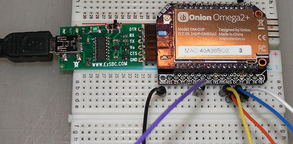
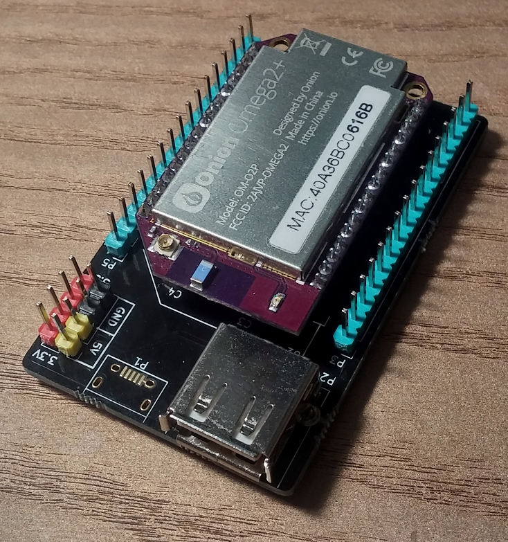
WereCatf's intent with her Omega board is to connect to it with female jumper wires. Those wanting a breadboardable dock (simply use two small boards as in my photo) should take a look at Charles Hallard's GPIO version board. The bare boards are available from PCBs.io. In my initial testing - the boards just arrived here and require soldering some tiny parts - my Omegas work fine on his docks. Have tested with several UARTs, this is pictured. If you buy this UART, I would replace the switch with a jumper wire to remove any possibility of sending 5V to the Omega.
-
This post is deleted!
-
@Chris-Stratton Thanks, post corrected.
-
@Ken-Conrad looks good, but I may require USB host...
Waiting for @Daniel-Andrade PCB...
-
I received my PCBs today and I see that I've made a mistake: the ESD-protection prevents the USB-host port from working right. Removing the resistor and capacitor (or not soldering them in the first place) allows it to work. Leaving those out just means a slightly less protected USB-port, otherwise the board works fine, so I'm not in a hurry to design a fix. I'll do it when I feel like it.
(The microUSB-port is missing, because Chinaman sent me wrong connectors -- they don't match the holes on the PCB. Just gotta wait for the right ones to arrive in the mail.)
-
@WereCatf said in DIY Onion-Mini-Dock:
I received my PCBs today and I see that I've made a mistake: the ESD-protection prevents the USB-host port from working right. Removing the resistor and capacitor (or not soldering them in the first place) allows it to work. Leaving those out just means a slightly less protected USB-port, otherwise the board works fine, so I'm not in a hurry to design a fix. I'll do it when I feel like it.
(The microUSB-port is missing, because Chinaman sent me wrong connectors -- they don't match the holes on the PCB. Just gotta wait for the right ones to arrive in the mail.)Thanks mister.
-
@Adalberto-Caldeira-Brant-Filho said in DIY Onion-Mini-Dock:
Thanks mister.
Please! She is a LADY :slight_smile:
-
I got the missing microUSB-connectors yesterday and just soldered one down. I gotta say, they are a bitch to hand-solder! I gotta think of a better way of doing it.
-
Folding up the shield on the back can help (though perhaps more with minis than micros)
Extending the pads further outside the outline can also be good, as you can then get solder to flow from the iron accessible part to where it is needed.
Ultimately though the solution is a hot air station - prices have fallen so far, it's just not worth the frustration to try to make do without.
If you had a yet untouched board, you could try the hot plate method, preferably with solder paste but possible by pre-tinning the pads, placing the connector, and then maybe adding some liquid flux as it reaches temperature.
-
@WereCatf Agree here about the micro USB socket ... that is why last month I suggested a mini USB connector for hand soldering. A few years ago mini cables came with digital cameras and lots of other hardware - now they are dirt cheap. Also, I found a third hand tweezers that is useful for holding any tiny part in place while I solder.
Chris's suggestions are good, too.
-
@Ken-Conrad are you happy with the tweezers? do they lock in place very well?
-
@Chris-Stratton I do have one and a tube of solder paste. It's a Yihua 898D+ -- pretty cheap and very handy, I just ain't very experienced in the Black Arts of SMD-work (TM) yet!
") That said, I just soldered another microUSB-connector with it and it went easier this time around. It's just a matter of lack of practice.
That said, I just soldered another microUSB-connector with it and it went easier this time around. It's just a matter of lack of practice.Now, I dunno what to do with these three extra PCBs. It's not like I need more than one dock myself..hm.
-
@WereCatf Where are you from, maybe i can take one from your hands?

Or you can use them to master the black art of smd

-
@Douglas-Kryder Happy? Yes. Hand soldering may be old school, I use it to just get the job done. Those tweezers are spring loaded so hold small parts nicely. If you don't like the tweezers that they ship with the unit just about any other tweezers would fit in the clamp. I find the third hand perfect to hold a 0602, 0805 etc cap or resistor in place on a board over the tiny traces while moving in with the fine tip on my soldering iron. I may also use some tape to hold the board to my work table. I like .020"/ .5mm solder for tiny parts. For the mini USB connectors - since I am connecting just the 5V and ground legs - I cut the three other center legs off, so there won't be any solder bridges between possible USB signals in the cable.
In essence, the problem is that the very act of touching a soldering tip to a tiny placed part displaces the part off the board trace or solder pad ... this tool can grip and hold the part in place long enough to solder the first solder point on the part.
-
@J-Tech I live in Finland and I doubt you do live here. I could send one in the mail, but I have no idea how much it costs to send anything to another country -- never had a reason to do so before.
-
@Ken-Conrad said in DIY Onion-Mini-Dock:
In essence, the problem is that the very act of touching a soldering tip to a tiny placed part displaces the part off the board trace or solder pad ... this tool can grip and hold the part in place long enough to solder the first solder point on the part.
This is why I like solder paste + hot air gun so much: I have a nervous-system issue which causes both my hands and fingers to tremor a lot -- sometimes I can't even hold a glass in my hands unless I use both hands -- and I have trouble soldering even regular through-hole components, but with a hot air gun I don't have to be so precise. I can take as long as I want to with applying the solder paste and dropping the component in place, and one doesn't even have to be terribly precise with the paste, either, and, best of all, no need to worry about accidentally pushing components out of place with shaking iron!