CAN Bus: using MCP2515 with Omega2
-
2) IRQ GPIO in DTS
After confirming that the MCP251x driver is initialized as half-duplex mode as desired, I came back to investigate IRQ issue.
I measured the GPIO11 with an oscilloscope. The result was exactly like you mentioned.
BPIO11 was always HIGH and never tirggered even though there are incoming packets.Is there a quick way to check if GPIO11 is released from Omega2's bootloader for general-purpose use?
In other word, how can I check the IRQ is properly configured on GPIO11?
-
@DumTux said in CAN Bus: using MCP2515 with Omega2:
Is there a quick way to check if GPIO11 is released from Omega2's bootloader for general-purpose use?
If you can "export" it via the '/sys/class/gpio' interface (before loading your driver that may try to use it, and possibly block it even if not successful establishing it as IRQ), then it should be available.
However, when you are using unpatched 22.03, the
/sys/class/gpiointerface (deprecated by now) will have completely strange GPIO numbering: GPIO 0..31 -> 480..511, GPIO 32..63 = 448..479.
So you'd need to export GPIO 491 to get GPIO 11.I am using a patch on top of 22.03 to bring back the
gpio-baseDT property which allows to revert the numbering back to what it was in 19.07. New projects should use the new gpiod interface, but this is not entirely ready yet, see my attempt to find out what the status of GPIOs in OpenWrt is.
-
This post is deleted!
-
@DumTux said in CAN Bus: using MCP2515 with Omega2:
Fabulous!
After a few seconds of power on, GPIO11 went to HIGH status and never dropped to LOW level while MCP2515 operating. Instead, after CAN bus enabling, the GPIO11 voltage was ~2.0V.
I think it was because MCP2515 was trying to pull down, while Omega2 is trying to output HIGH.But with that GPIO number fixing, it dropped to LOW after CAN bus enabling.
Here's the results.root@OpenWrt:~# ls /sys/class/gpio/ export gpiochip416 gpiochip448 gpiochip480 unexport root@OpenWrt:~# echo 491 > /sys/class/gpio/export root@OpenWrt:~# ls /sys/class/gpio/ export gpio491 gpiochip416 gpiochip448 gpiochip480 unexport root@OpenWrt:~# cat /sys/class/gpio/gpio491/direction out root@OpenWrt:~# echo in > /sys/class/gpio/gpio491/direction root@OpenWrt:~# cat /sys/class/gpio/gpio491/direction in root@OpenWrt:~# insmod /lib/modules/5.10.146/mcp251x.ko root@OpenWrt:~# ip l | grep can 6: can0: <NOARP,ECHOmtu 16 qdisc noop state DOWN mode DEFAULT group default qlen 10 link/can root@OpenWrt:~# ip link set can0 up type can bitrate 125000 root@OpenWrt:~#Just after this
ip link set can0 upcommand ran, the GPIO11 dropped to LOW.
I think MCP2515 is pulling down the INT# pin as it is constantly receiving packets from external sensor.I'll keep my further working results posted.
-
@luz @Lazar-Demin @crispyoz and all!
I am still having trouble with CAN bus driving.Current behavior
- I set GPIO11 as input and load the MCP251x kernel module as per above discussion.
- Now enable
can0and send packets using these commands.
root@OpenWrt:~# ip link set can0 up type can bitrate 125000
root@OpenWrt:~# cansend can0 01a#11223344AABBCCDD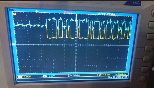
- I can see the waveform on bus by oscilloscope correctly.
- Restart the bus as loopback mode to test somthing different.
root@OpenWrt:~# ip link set can0 down root@OpenWrt:~# ip link set can0 up type can bitrate 125000 loopback on- Now the INT# (GPIO11) falls to LOW. MCP2515 stopped working.
*** MCP2515 does not recover even though I disable/enable the bus again like this.
root@OpenWrt:~# ip link set can0 down root@OpenWrt:~# ip link set can0 up type can bitrate 125000- I have to turn off the board power and turn it on again to make MCP2515 INT# recovered.
dmesgshows nothing except success logs like this during all these operation.
... [ 68.586340] mcp251x spi0.1 can0: MCP2515 successfully initialized. [ 69.759118] IPv6: ADDRCONF(NETDEV_CHANGE): can0: link becomes ready [ 124.360819] IPv6: ADDRCONF(NETDEV_CHANGE): can0: link becomes ready ...- The same situation goes for when I connect external sensor module, that emits CAN message periodically.
- As soon as any external packet is coming in, the MCP2515 INT# falls to LOW. I can read nothing via
candump. - All this behavior were the same no matter of setting GPIO11 as IN or not before loading the MCP251x kernel module.
Questions
- Is this still IRQ problem?
- Is there any way to check MCP2515 resistor values using
canutilspackage commands? - Is there other reading method except
candump? For example, instead of inturrupt-basedcandump, manual polling.
-
I am going to try to modify the bootloader to not handle GPIO11 for the dock power supply.
There is a bootloader on OnionIoT GitHub account, but it seems like outdated.
And I could not find the current OpenWrt 22.03 build using it.Thus, I guess GPIO11 handling is somewhere patched inside OpenWrt 22.03's specific config files.
I could see some MediaTek related config patches underopenwrt/package/boot/uboot-mediatek/.
There I either cannot find specific configs related to Omega2.
As MT76x8 is used in router products a lot, I don't believe the Omega2 specific config will be under this location.Where can I find the OpenWrt 22.03 bootloader for Omega2?
-
@DumTux The bootloader is independent of the firmware. If you've reflashed your Omega2, it will still be running the factory bootloader.
The factory bootloader is compiled from this source code: https://github.com/OnionIoT/omega2-bootloader/
GPIO11 is set high to be compatible with the reset button on the Omega2 Docks. You can find that here in the bootloader: https://github.com/OnionIoT/omega2-bootloader/blob/master/lib_mips/board.c#L3028When you've compiled your own bootloader, follow these instructions to update your device: http://docs.onion.io/omega2-docs/Web-Recovery-flash-bootloader.html
-
void gpio_init(void)
{
  ....
  RALINK_REG(RT2880_REG_PIODIR+0x04)=val;

  /*
  //zh@onion.io
  //setting GPIO 11 High, required for the reset button to work
  val=RALINK_REG(RT2880_REG_PIODIR);
  val|=1<<11;
  RALINK_REG(RT2880_REG_PIODIR) = val; // GPIO 11 direction output
  val=RALINK_REG(RT2880_REG_PIODATA);
  val|=1<<11;
  RALINK_REG(RT2880_REG_PIODATA) = val; // GPIO 11 High
  */

  //jeffzhou@onion.io
  //adding for read wifi MAC address.
  unsigned char macbuf[6];
	raspi_read(macbuf, CFG_FACTORY_ADDR - CFG_FLASH_BASE + 0x04, 6);
	printf("wifi mac address = %02X%02X%02X%02X%02X%02X.\n",
      macbuf[0],macbuf[1],macbuf[2],macbuf[3],macbuf[4],macbuf[5]);
}
I commented the GPIO11 related part in the bootloader source code, and built it.
Just usedmakecommand.After entering to Web recovery mode on Omega2's boot, I went to uBoot upgrade page.
There was Very dangerous warning, but I proceeded.
And after done, that dangerous result happened - not booting.
Is there some
makeoption to build a bootloader specfic for Omega2+ ?
-
As a comparison, this is normal booting screenshot from the factory bootloader.
It is showing DRAM size 128MB, while my above wrong bootloader shows as 64MB.
Also, flash memory is wrongly recognized.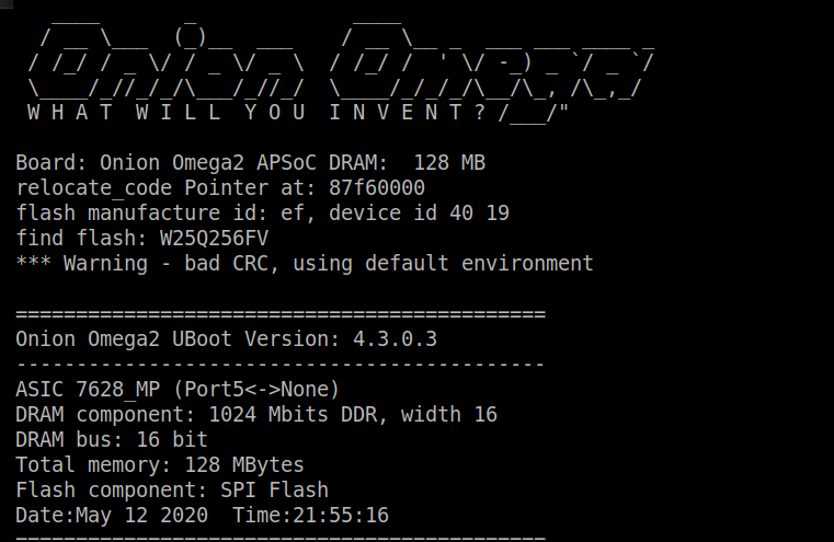
-
@DumTux Make sure to run
setup_env.shand then you can usebuild.shto build the bootloader binaries.
-
@Lazar-Demin
How can I build a U-Boot image for Omega2+ ?
-
@DumTux The process is:
git clone https://github.com/OnionIoT/omega2-bootloader/
cd omega2-bootloader
./setup_env.sh
chmod +x build.sh
./build.shThis produces 2 files:
uboot-omega2-<date>.bin
uboot-omega2p-<date>.binThe latter is the Omega2+ uboot
-
@crispyoz @Lazar-Demin
Yes, it worked. I choose theomgega2-bootloaderinstead ofomega2p-bootloaderaccidentally.
After soldering with a brand new Omeba2S+ module, I carefully upgraded bootloader.Here's the pre-compiled bootloader for others' future reference.
https://github.com/dumtux/omega2-bootloader/releases/tag/tower-bootloader-v0.1After disabling GPIO11 default behavior from Omega2's bootloader, I could see some different behavior of MCP2515 kernel driver.
I could see some short impulses while initializing MCP2515 driver and enablingcan0interface.
I didn't see such impulses before with the default bootloader.I'll keep posting further results.
-
@DumTux
AFAIK the main problem is related to the wrong GPIO/IRQ mapping:
https://forum.openwrt.org/t/can-mcp2515-gpio-irq-problem/92879/3Maybe luz or Lazar could give a hint ?
-
@Gerhard-Bertelsmann Yes, the 19.07 version of
gpio-mt7621.cinterrupt routing implementation is broken for GPIO interrupts assigned via DT.I made ugly patches to fix that back then, I can dig them out if someone wants to use them, but I can't exactly recommend (it was kind of an emergency hack for an urgent project).
As far as I know, the issue should be fixed in the 22.03 version of
gpio-mt7621.c, as the entire driver has been reworked to align with other modern GPIO drivers and handles the banks differently.But I haven't had the chance to test it so far, and the link to the OpenWrt forum you posted saying it is not yet fixed in 21.02 makes me doubt a bit, because I thought the rework already happened in the 21.02 time frame, but I can't verify or test that right now.
-
@Gerhard-Bertelsmann
I experienced similar error messages when I used the wrong GPIO number.
For example, I tried this.
interrupts = <75 0x02>
And it gave very similar error as yours on kernel module loading.As far as I used the right GPIO number 11, the kernel module loading was just successful.
I don't have a clue if this means the issue was eliminated in 22.03.When I connect two boards via CAN bus, I could only enable CAN driver from one board.
Currently, I am in a different situation after disabling GPIO11's default behavior of the bootloader.
I can enable both side drivers. And each board can send CAN packets bycansend.
However, the interrupt is not invoking andcandumpstill prints nothing.
-
@luz said in CAN Bus: using MCP2515 with Omega2:
I made ugly patches to fix that back then, I can dig them out if someone wants to use them, but I can't exactly recommend (it was kind of an emergency hack for an urgent project).
I would be interested in this patch
As far as I know, the issue should be fixed in the 22.03 version of
gpio-mt7621.c, as the entire driver has been reworked to align with other modern GPIO drivers and handles the banks differently.I switched to 22.03 but the problem is still present
-
I just did another experiment.
I disconnected external sensor.Omega2 -> MCP2515 -> (open) -> OscilloscopeIf I enable the CAN bus like this, I can see output CAN packet from the oscilloscope.
ip link set can0 up type can bitrate 125000
cansend can0 01a#112233
Next, I enabled CAN bus with loopback mode.
ip link set can0 down
ip link set can0 up type can bitrate 125000 loopback on
cansend can0 01a#112233
No CAN packet waveform I can see!
To see it again, I should re-enable the CAN bus without loopback mode.ip link set can0 down ip link set can0 up type can bitrate 125000 loopback off cansend can0 01a#112233Any thought from this loopback mode behavior?
-
@luz
I also would like to see your patches as @Gerhard-Bertelsmann said.
Is it somewhere in public repo?
-
@DumTux said in CAN Bus: using MCP2515 with Omega2:
Next, I enabled CAN bus with loopback mode.
ip link set can0 down
ip link set can0 up type can bitrate 125000 loopback on
cansend can0 01a#112233
No CAN packet waveform I can see!
that's the usual behaviour in loopback mode. Packets are not transmitted to the transceiver.
I use the loopback mode for testing purpose. If this works (received the same data as send) everything is fine with the communication to the CAN controller.